


RL78/G1A APPENDIX A REVISION HISTORY
(4/5)
Page Description Classification
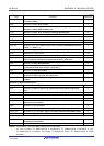
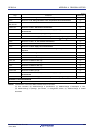
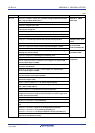
CHAPTER 18 STANDBY FUNCTION
p.758 Modification of Table 18-1. Operating Statuses in HALT Mode (c)
p.760, 761 Modification of figure and note in Figure 18-4. HALT Mode Release by Reset (c)
p.762 Modification of caution 1 in 18.3.2 (1) STOP mode setting and operating statuses (c)
p.764 Deletion of caution 1 in Table 18-2. Operating Statuses in STOP Mode (c)
p.764, 765 Modification of note 2 and addition of remark 2 to Figure 18-5. STOP Mode Release by Interrupt
Request Generation
(c)
p.766 Modification of figure and note in Figure 18-6. STOP Mode Release by Reset (c)
p.767 Modification of description in 18.3.3 (1) SNOOZE mode setting and operating statuses (c)
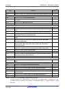
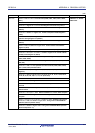
CHAPTER 19 RESET FUNCTION
p.769 Modification of description and cautions 1, 3 in CHAPTER 19 RESET FUNCTION (c)
p.771, 772 Modification of figure and note 2 in Figures 19-2, 19-3 (c)
p.773 Modification of description in Table 19-1. Operation Statuses During Reset Period (c)
p.774 Modification of description and note 2 in Table 19-2. Hardware Statuses After Reset
Acknowledgment
(c)
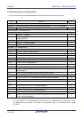
CHAPTER 20 POWER-ON-RESET CIRCUIT
p.781 Modification of description and addition of note to 20.1 Functions of Power-on-reset Circuit (c)
p.783 to 785 Modification of figure and notes in Figure 20-2. Timing of Generation of Internal Reset Signal by
Power-on-reset Circuit and Voltage Detector
(c)
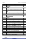
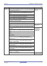
CHAPTER 21 VOLTAGE DETECTOR
p.788 Modification of description in 21.1 Functions of Voltage Detector (c)
p.795 Modification of Figure 21-4. Timing of Voltage Detector Internal Reset Signal Generation (Option
Byte LVIMDS1, LVIMDS0 = 1, 1)
(c)
p.796 Addition of note to 21.4.2 When used as interrupt mode (c)
p.797 Modification of figure and addition of notes 2, 3 to Figure 21-5. Timing of Voltage Detector Internal
Interrupt Signal Generation (Option Byte LVIMDS1, LVIMDS0 = 0, 1)
(c)
p.798 Addition of note to 21.4.3 When used as interrupt and reset mode (c)
p.799 to 802 Modification of figure and addition of note 4 to Figure 21-6. Timing of Voltage Detector Reset
Signal and Interrupt Signal Generation (Option Byte LVIMDS1, LVIMDS0 = 1, 0)
(c)
p.802 Modification of Figure 21-7. Processing Procedure After an Interrupt Is Generated (c)
p.803 Modification of Figure 21-8. Initial Setting of Interrupt and Reset Mode (c)
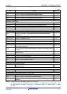
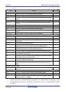
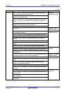
CHAPTER 22 SAFETY FUNCTIONS
p.806 Modification of remark in 22.1 Overview of Safety Functions (c)
p.812 Modification of caution and remarks 1 to 4 in Figure 22-7. Format of RAM Parity Error Control
Register (RPECTL)
(c)
p.815 Addition of figure and note to Figure 22-10. Invalid access detection area (c)
CHAPTER 24 OPTION BYTE
p.824 Modification of description and addition of caution to 24.1 Functions of Option Bytes (c)
p.825 Modification of description in 24.1.1 User option byte (000C0H to 000C2H/010C0H to 010C2H) (c)
p.826 Modification of caution in Figure 24-1. Format of User Option Byte (000C0H/010C0H) (c)
p.827, 828 Addition of caution 2 to Figure 24-2. Format of User Option Byte (000C1H/010C1H) (c)
p.829 Modification of description and caution in Figure 24-3. Format of User Option Byte
(000C2H/010C2H)
(c)
Remark “Classification” in the above table classifies revisions as follows.
(a): Error correction, (b): Addition/change of specifications, (c): Addition/change of description or note,
(d): Addition/change of package, part number, or management division, (e): Addition/change of related
documents
R01UH0305EJ0200 Rev.2.00 972
Jul 04, 2013