


RL78/G1A CHAPTER 4 PORT FUNCTIONS
R01UH0305EJ0200 Rev.2.00 137
Jul 04, 2013
4.6 Cautions When Using Port Function
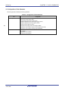
4.6.1 Cautions on 1-bit manipulation instruction for port register n (Pn)
When a 1-bit manipulation instruction is executed on a port that provides both input and output functions, the output
latch value of an input port that is not subject to manipulation may be written in addition to the targeted bit.
Therefore, it is recommended to rewrite the output latch when switching a port from input mode to output mode.
<Example> When P10 is an output port, P11 to P16 are input ports (all pin statuses are high level), and the port
latch value of port 1 is 00H, if the output of output port P10 is changed from low level to high level via a
1-bit manipulation instruction, the output latch value of port 1 is FFH.
Explanation: The targets of writing to and reading from the Pn register of a port whose PMnm bit is 1 are the output
latch and pin status, respectively.
A 1-bit manipulation instruction is executed in the following order in the RL78/G1A.
<1> The Pn register is read in 8-bit units.
<2> The targeted one bit is manipulated.
<3> The Pn register is written in 8-bit units.
In step <1>, the output latch value (0) of P10, which is an output port, is read, while the pin statuses of
P11 to P16, which are input ports, are read. If the pin statuses of P11 to P16 are high level at this time,
the read value is FEH.
The value is changed to FFH by the manipulation in <2>.
FFH is written to the output latch by the manipulation in <3>.
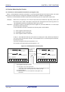
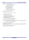
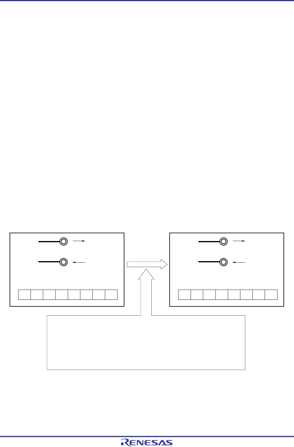
Figure 4-12. Bit Manipulation Instruction (P10)
Low-level output
1-bit manipulation
instruction
(set1 P1.0)
is executed for P10
bit.
Pin status: High-level
P10
P11 to P16
Port 1 output latch
00000000
High-level output
Pin status: High-level
P10
P11 to P16
Port 1 output latch
01111111
1-bit manipulation instruction for P10 bit
<1> Port register 1 (P1) is read in 8-bit units.
• In the case of P10, an output port, the value of the port output latch (0) is read.
• In the case of P11 to P16, input ports, the pin status (1) is read.
<2> Set the P10 bit to 1.
<3> Write the results of <2> to the output latch of port register 1 (P1)
in 8-bit units.