


RL78/G1A CHAPTER 10 WATCHDOG TIMER
10.2 Configuration of Watchdog Timer
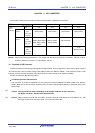
The watchdog timer includes the following hardware.
<R>
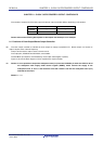
Table 10-1. Configuration of Watchdog Timer
Item Configuration
Counter Internal counter (17 bits)
Control register Watchdog timer enable register (WDTE)
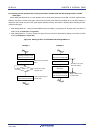
How the counter operation is controlled, overflow time, window open period, and interval interrupt are set by the option
byte.
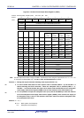
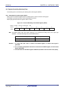
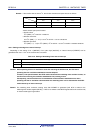
Table 10-2. Setting of Option Bytes and Watchdog Timer
Setting of Watchdog Timer Option Byte (000C0H)
Watchdog timer interval interrupt Bit 7 (WDTINT)
Window open period Bits 6 and 5 (WINDOW1, WINDOW0)
Controlling counter operation of watchdog timer Bit 4 (WDTON)
Overflow time of watchdog timer Bits 3 to 1 (WDCS2 to WDCS0)
Controlling counter operation of watchdog timer
(in HALT/STOP mode)
Bit 0 (WDSTBYON)
Remark For the option byte, see CHAPTER 24 OPTION BYTE.
<R>
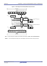
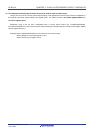
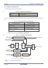
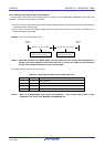
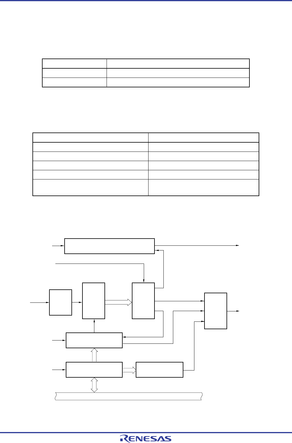
Figure 10-1. Block Diagram of Watchdog Timer
f
IL
WDTON of option
byte (000C0H)
WDTINT of option
byte (000C0H)
Interval time controller
(Count value overflow time × 3/4 + 1/2f
IL
)
Interval time interrupt
WDCS2 to WDCS0 of
option byte (000C0H)
Clock
input
controller
Internal
counter
(17 bits)
Selector
Overflow signal
Reset
output
controller
Internal reset signal
Count clear
signal
Window size
decision signal
Window size check
Watchdog timer enable
register (WDTE)
Write detector to
WDTE except ACH
Internal bus
WINDOW1 and
WINDOW0 of option
byte (000C0H)
f
IL
/2
6
to f
IL
/2
16
Detection of writing ACH to WDTE
Remark f
IL: Low-speed on-chip oscillator clock
R01UH0305EJ0200 Rev.2.00 334
Jul 04, 2013