


RL78/G1A CHAPTER 6 TIMER ARRAY UNIT
R01UH0305EJ0200 Rev.2.00 227
Jul 04, 2013
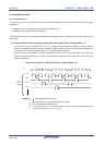
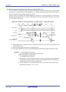
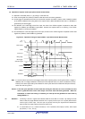
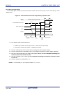
(3) Operation of capture mode (input pulse interval measurement)
<1> Operation is enabled (TEmn = 1) by writing 1 to the TSmn bit.
<2> Timer count register mn (TCRmn) holds the initial value until count clock generation.
<3> A start trigger is generated at the first count clock after operation is enabled. And the value of 0000H is loaded
to the TCRmn register and counting starts in the capture mode. (When the MDmn0 bit is set to 1, INTTMmn is
generated by the start trigger.)
<4> On detection of the valid edge of the TImn input, the value of the TCRmn register is captured to timer data
register mn (TDRmn) and INTTMmn is generated. However, this capture value is no meaning. The TCRmn
register keeps on counting from 0000H.
<5> On next detection of the valid edge of the TImn input, the value of the TCRmn register is captured to timer data
register mn (TDRmn) and INTTMmn is generated.
Figure 6-27. Operation Timing (In Capture Mode : Input Pulse Interval Measurement)
Note If a clock has been input to TImn (the trigger exists) when capturing starts, counting starts when a trigger is
detected, even if no edge is detected. Therefore, the first captured value (<4>) does not determine a pulse
interval (in the above figure, 0001 just indicates two clock cycles but does not determine the pulse interval)
and so the user can ignore it.
Caution In the first cycle operation of count clock after writing the TSmn bit, an error at a maximum of one
clock is generated since count start delays until count clock has been generated. When the
information on count start timing is necessary, an interrupt can be generated at count start by
setting MDmn0 = 1.
Remarks 1. The timing is shown in Figure 6-25 indicates while the noise filter is not used. By making the noise
filter on-state, the edge detection becomes 2 f
MCK cycles (it sums up to 3 to 4 cycles) later than the
normal cycle of TImn input. The error per one period occurs by the asynchronous between the
period of the TImn input and that of the count clock (f
MCK).
2. m: Unit number (m = 0), n: Channel number (n = 0 to 7 (however, timer input pin (TImn), timer output
pin (TOmn) : n = 0, 1, 3 to 7))
fMCK
(fTCLK)
TSmn (write)
TEmn
TImn input
<1>
<2>
Rising edge
<4>
TCRmn Initial value
m−1
m
TDRmn
Start trigger
detection signal
<3>
0000
m
Edge detection
0001
Note
0000
INTTMmn
<5>
0000 0001
<3>
Note
Edge detection
When MDmn0 = 1
<R>