


RL78/G1A CHAPTER 21 VOLTAGE DETECTOR
21.4.2 When used as interrupt mode
<R>
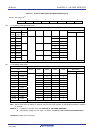
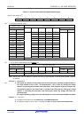
Specify the operation mode (the interrupt mode (LVIMDS1, LVIMDS0 = 0, 1)) and the detection voltage (VLVD) by using
the option byte 000C1H.
The operation is started in the following initial setting state when the interrupt mode is set.
• Bit 7 (LVISEN) of the voltage detection register (LVIM) is set to 0 (disable rewriting of voltage detection level
register (LVIS))
• The initial value of the voltage detection level select register (LVIS) is set to 01H.
Bit 7 (LVIMD) is 0 (interrupt mode).
Bit 0 (LVILV) is 1 (low-voltage detection level: V
LVD).
• Operation in LVD interrupt mode
In the interrupt mode (option byte LVIMDS1, LVIMDS0 = 0, 1), the state of an internal reset by LVD is retained
until the supply voltage (V
DD) exceeds the voltage detection level (VLVD) after power is supplied (after the first
release of the POR). The internal reset is released when the supply voltage (V
DD) exceeds the voltage detection
level (V
LVD).
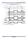
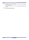
An interrupt request signal by LVD (INTLVD) is generated, when the supply voltage (VDD) falls below the voltage
detection level (V
LVD) or when the supply voltage (VDD) exceeds the voltage detection level (VLVD) after the second
release of the POR. When the voltage falls, this LSI should be placed in the STOP mode, or placed in the reset
state by controlling the externally input reset signal, before the voltage falls below the operating voltage range
defined in 29.4 or 30.4 AC characteristics. When restarting the operation, make sure that the operation voltage
has returned within the range of operation.
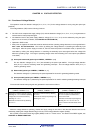
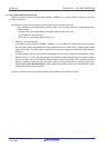
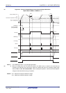
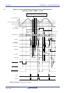
Figure 21-5 shows the timing of the interrupt request signal generated in the LVD interrupt mode.
R01UH0305EJ0200 Rev.2.00 762
Jul 04, 2013