


RL78/G1A CHAPTER 7 REAL-TIME CLOCK
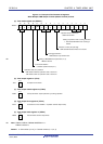
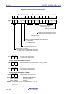
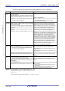
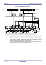
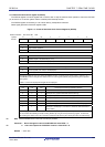
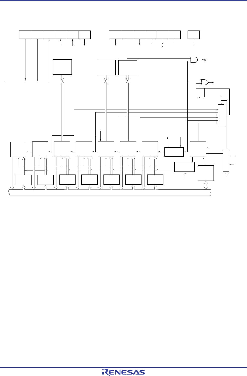
Figure 7-1. Block Diagram of Real-time Clock
INTRTC
RTCE
WUTMM
CK0
RCLOE1
AMPM CT2 CT1 CT0
RTCE
AMPM
CT0 to CT2
WUTMMCK0
f
RTC
f
SUB
f
IL
RWAIT
WALE WALIE WAFG RWAIT
RWST
RIFG
RWST
RIFG
Real-time clock control register 1
Real-time clock control register 0
Subsystem clock supply mode
control register (OSMC)
Alarm week
register
(ALARMWW)
(7-bit)
Alarm hour
register
(ALARMWH)
(6-bit)
Alarm minute
register
(ALARMWM)
(7-bit)
Year count
register
(YEAR)
(8-bit)
Month count
register
(MONTH)
(5-bit)
Week count
register
(WEEK)
(3-bit)
Day count
register
(DAY)
(6-bit)
Hour count
register
(HOUR)
(6-bit)
Minute count
register
(MIN)
(7-bit)
Second
count
register
(SEC)
(7-bit)
Wait control
0.5
seconds
Internal
counter
(16-bit)
Selector
Selector
Buffer
Buffer
Buffer
Buffer Buffer Buffer Buffer
Count enable/
disable circuit
Watch error
correction
register
(SUBCUD)
(8-bit)
Internal bus
1 month
1 day 1 hour
1 minute
RTC1HZ
1 seconds
1 year
Matched
<R>
Caution The count of year, month, week, day, hour, minutes and second can only be performed when a
subsystem clock (fSUB = 32.768 kHz) is selected as the operation clock of the real-time clock.
When the low-speed oscillation clock (f
IL = 15 kHz (TYP.)) is selected, only the constant-period
interrupt function is available. The 25- to 32-pin products have the constant-period interrupt
function only, because these products have no subsystem clock.
However, the constant-period interrupt interval when f
IL is selected will be calculated with the
constant-period (the value selected with RTCC0 register) × f
SUB/fIL.
R01UH0305EJ0200 Rev.2.00 294
Jul 04, 2013