


RL78/G1A CHAPTER 9 CLOCK OUTPUT/BUZZER OUTPUT CONTROLLER
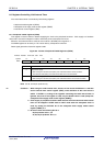
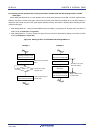
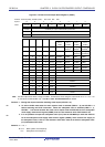
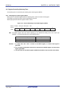
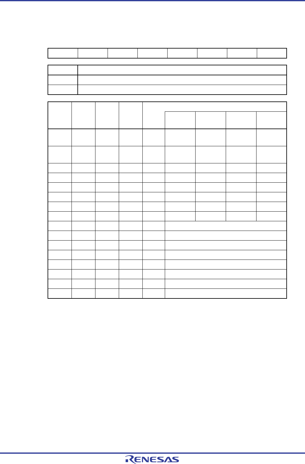
Figure 9-2. Format of Clock Output Select Register n (CKSn)
Address: FFFA5H (CKS0), FFFA6H (CKS1) After reset: 00H R/W
Symbol <7> 6 5 4 3 2 1 0
CKSn PCLOEn 0 0 0 CSELn CCSn2 CCSn1 CCSn0
PCLOEn PCLBUZn pin output enable/disable specification
0 Output disable (default)
1 Output enable
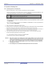
PCLBUZn pin output clock selection CSELn CCSn2 CCSn1 CCSn0
f
MAIN =
5 MHz
fMAIN =
10 MHz
fMAIN =
20 MHz
fMAIN =
32 MHz
0 0 0 0 fMAIN 5 MHz
Setting
prohibited
Note
Setting
prohibited
Note
Setting
prohibited
Note
0 0 0 1 fMAIN/2 2.5 MHz 5 MHz
Setting
prohibited
Note
Setting
prohibited
Note
0 0 1 0 fMAIN/2
2
1.25 MHz 2.5 MHz 5 MHz 8 MHz
Note
0 0 1 1 fMAIN/2
3
625 kHz 1.25 MHz 2.5 MHz 4 MHz
0 1 0 0 fMAIN/2
4
312.5 kHz 625 kHz 1.25 MHz 2 MHz
0 1 0 1 fMAIN/2
11
2.44 kHz 4.88 kHz 9.76 kHz 15.63 kHz
0 1 1 0 fMAIN/2
12
1.22 kHz 2.44 kHz 4.88 kHz 7.81 kHz
0 1 1 1 fMAIN/2
13
610 Hz 1.22 kHz 2.44 kHz 3.91 kHz
1 0 0 0 fSUB 32.768 kHz
1 0 0 1 fSUB/2 16.384 kHz
1 0 1 0 fSUB/2
2
8.192 kHz
1 0 1 1 fSUB/2
3
4.096 kHz
1 1 0 0 fSUB/2
4
2.048 kHz
1 1 0 1 fSUB/2
5
1.024 kHz
1 1 1 0 fSUB/2
6
512 Hz
1 1 1 1 fSUB/2
7
256 Hz
Note Use the output clock within a range of 8 MHz. Furthermore, when using the output clock at 2.7 V ≤ V
DD < 4.0
V, can be use it within 8 MHz only. See 29.4 or 30.4 AC Characteristics for details.
Cautions 1. Change the output clock after disabling clock output (PCLOEn = 0).
2. To shift to STOP mode when the main system clock is selected (CSELn = 0), set PCLOEn = 0
before executing the STOP instruction. When the subsystem clock is selected (CSELn = 1),
PCLOEn = 1 can be set because the clock can be output while the RTCLPC bit of the subsystem
clock supply mode control register (OSMC) is set to 0 and moreover while STOP mode is set.
<R>
3. It is not possible to output the subsystem clock (f
SUB) from the PCLBUZn pin while the RTCLPC
bit of the subsystem clock supply mode control register (OSMC), which controls the supply of
the subsystem clock, is set to 1 and moreover while HALT mode is set with the subsystem clock
(f
SUB) selected as CPU clock.
<R>
Remarks 1. n = 0, 1
2. f
MAIN: Main system clock frequency
fSUB: Subsystem clock frequency
R01UH0305EJ0200 Rev.2.00 330
Jul 04, 2013