


RL78/G1A CHAPTER 6 TIMER ARRAY UNIT
R01UH0305EJ0200 Rev.2.00 243
Jul 04, 2013
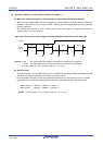
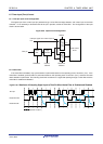
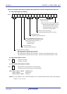
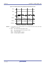
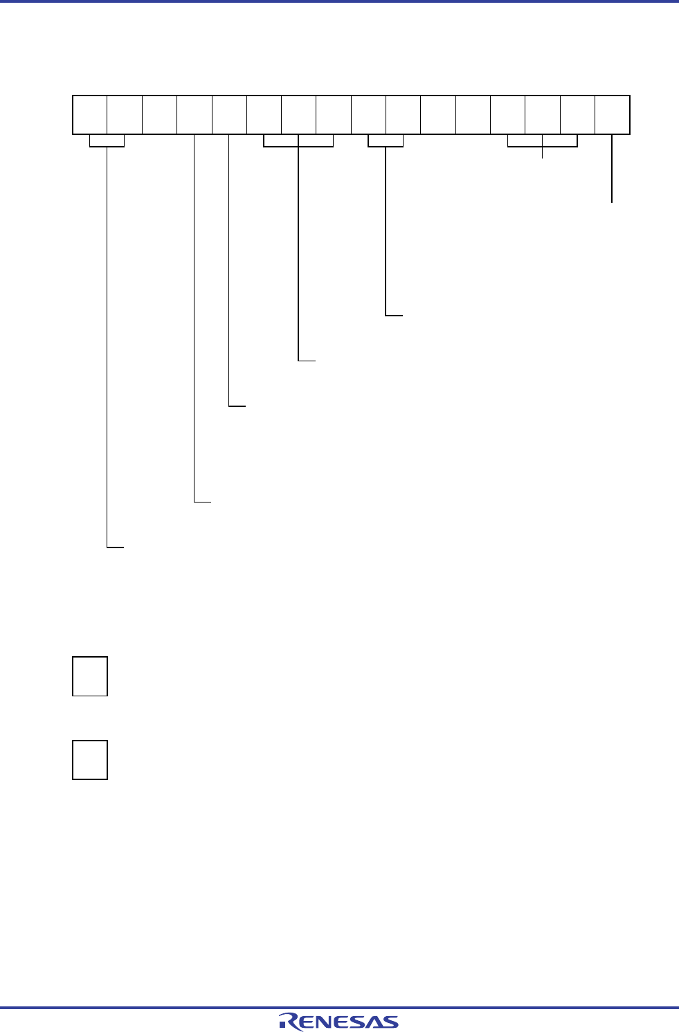
Figure 6-43. Example of Set Contents of Registers During Operation as Interval Timer/Square Wave Output (1/2)
(a) Timer mode register mn (TMRmn)
15 14 13 12 11 10 9 8 7 6 5 4 3 2 1 0
TMRmn
CKSmn1
1/0
CKSmn0
1/0
0
CCSmn
0
M/S
Note
0/1
STSmn2
0
STSmn1
0
STSmn0
0
CISmn1
0
CISmn0
0
0
0
MDmn3
0
MDmn2
0
MDmn1
0
MDmn0
1/0
Operation mode of channel n
000B: Interval timer
Setting of operation when counting is started
0: Neither generates INTTMmn nor inverts
timer output when counting is started.
1: Generates INTTMmn and inverts timer
output when counting is started.
Selection of TImn pin input edge
00B: Sets 00B because these are not used.
Start trigger selection
000B: Selects only software start.
Setting of MASTERmn bit (channels 2, 4, 6)
0: Independent channel operation function.
Setting of SPLITmn bit (channels 1, 3)
0: 16-bit timer mode
1: 8-bit timer mode
Count clock selection
0: Selects operation clock (f
MCK).
Operation clock (f
MCK) selection
00B: Selects CKm0 as operation clock of channel n.
10B: Selects CKm1 as operation clock of channel n.
01B: Selects CKm2 as operation clock of channels 1, 3 (This can only be selected channels 1 and 3).
11B: Selects CKm3 as operation clock of channels 1, 3 (This can only be selected channels 1 and 3).
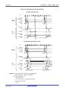
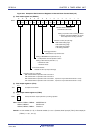
(b) Timer output register m (TOm)
Bit n
TOm
TOmn
1/0
0: Outputs 0 from TOmn.
1: Outputs 1 from TOmn.
(c) Timer output enable register m (TOEm)
Bit n
TOEm
TOEmn
1/0
0: Stops the TOmn output operation by counting operation.
1: Enables the TOmn output operation by counting operation.
Note TMRm2, TMRm4, TMRm6: MASTERmn bit
TMRm1, TMRm3: SPLITmn bit
TMRm0, TMRm5, TMRm7: Fixed to 0
Remark m: Unit number (m = 0), n: Channel number (n = 0 to 7 (however, timer input pin (TImn), timer output pin
(TOmn) : n = 0, 1, 3 to 7))