


RL78/G1A CHAPTER 13 SERIAL INTERFACE IICA
13.5.8 Interrupt request (INTIICA0) generation timing and wait control
The setting of bit 3 (WTIM0) of IICA control register 00 (IICCTL00) determines the timing by which INTIICA0 is
generated and the corresponding wait control, as shown in Table 13-2.
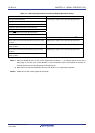
Table 13-2. INTIICA0 Generation Timing and Wait Control
Jul 04, 2013
During Slave Device Operation During Master Device Operation WTIM0
Address Data Reception Data Transmission Address Data Reception Data Transmission
9
Notes 1, 2
8
Note 2
8
Note 2
0 9 8 8
9
Notes 1, 2
9
Note 2
9
Note 2
1 9 9 9
Notes 1. The slave device’s INTIICA0 signal and wait period occurs at the falling edge of the ninth clock only when
there is a match with the address set to the slave address register 0 (SVA0).
At this point, ACK is generated regardless of the value set to the IICCTL00 register’s bit 2 (ACKE0). For a
slave device that has received an extension code, INTIICA0 occurs at the falling edge of the eighth clock.
However, if the address does not match after restart, INTIICA0 is generated at the falling edge of the 9th
clock, but wait does not occur.
2. If the received address does not match the contents of the slave address register 0 (SVA0) and extension
code is not received, neither INTIICA0 nor a wait occurs.
Remark The numbers in the table indicate the number of the serial clock’s clock signals. Interrupt requests and wait
control are both synchronized with the falling edge of these clock signals.
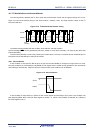
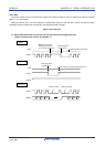
(1) During address transmission/reception
• Slave device operation: Interrupt and wait timing are determined depending on the conditions described in
Notes 1 and 2 above, regardless of the WTIM0 bit.
• Master device operation: Interrupt and wait timing occur at the falling edge of the ninth clock regardless of the
WTIM0 bit.
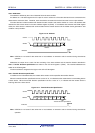
(2) During data reception
• Master/slave device operation: Interrupt and wait timing are determined according to the WTIM0 bit.
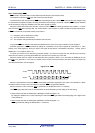
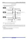
(3) During data transmission
• Master/slave device operation: Interrupt and wait timing are determined according to the WTIM0 bit.
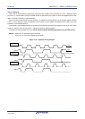
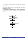
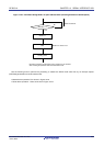
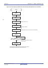
(4) Wait cancellation method
The four wait cancellation methods are as follows.
• Writing data to the IICA shift register 0 (IICA0)
• Setting bit 5 (WREL0) of IICA control register 00 (IICCTL00) (canceling wait)
• Setting bit 1 (STT0) of IICCTL00 register (generating start condition)
Note
• Setting bit 0 (SPT0) of IICCTL00 register (generating stop condition)
Note
Note Master only.
When an 8-clock wait has been selected (WTIM0 = 0), the presence/absence of ACK generation must be
determined prior to wait cancellation.
(5) Stop condition detection
INTIICA0 is generated when a stop condition is detected (only when SPIE0 = 1).
R01UH0305EJ0200 Rev.2.00 597