


RL78/G1A CHAPTER 4 PORT FUNCTIONS
R01UH0305EJ0200 Rev.2.00 106
Jul 04, 2013
4.3.2 Port registers (Pxx)
These registers set the output latch value of a port.
If the data is read in the input mode, the pin level is read. If it is read in the output mode, the output latch value is
read
Note
.
These registers can be set by a 1-bit or 8-bit memory manipulation instruction.
Reset signal generation clears these registers to 00H.
Note If P02, P03, P10 to P15, P20 to P27, P30, P31, P41, P50, P51, P70, P120, and P150 to P154 are set up as
analog inputs of the A/D converter, when a port is read while in the input mode, 0 is always returned, not the pin
level.
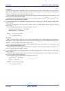
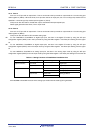
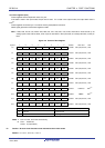
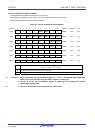
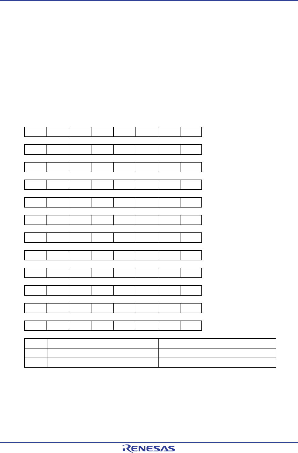
Figure 4-2. Format of Port Register
Symbol 7 6 5 4 3 2 1 0 Address After reset R/W
P0 0 P06 P05 P04 P03 P02 P01 P00 FFF00H 00H (output latch) R/W
P1 0 P16 P15 P14 P13 P12 P11 P10 FFF01H 00H (output latch) R/W
P2 P27 P26 P25 P24 P23 P22 P21 P20 FFF02H 00H (output latch) R/W
P3 0 0 0 0 0 0 P31 P30 FFF03H 00H (output latch) R/W
P4 0 0 0 0 P43 P42 P41 P40 FFF04H 00H (output latch) R/W
P5 0 0 0 0 0 0 P51 P50 FFF05H 00H (output latch) R/W
P6 0 0 0 0 P63 P62 P61 P60 FFF06H 00H (output latch) R/W
P7 P77 P76 P75 P74 P73 P72 P71 P70 FFF07H 00H (output latch) R/W
P12 0 0 0 P124 P123 P122 P121 P120 FFF0CH Undefined R/W
Note 1
P13 P137 0 0 0 0 0 0 P130 FFF0DH Note 2 R/W
Note 1
P14 0 0 0 0 0 0 P141 P140 FFF0EH 00H (output latch) R/W
P15 0 0 0 P154 P153 P152 P151 P150 FFF0FH 00H (output latch) R/W
Pmn Output data control (in output mode) Input data read (in input mode)
0 Output 0 Input low level
1 Output 1 Input high level
Notes 1. P121 to P124, and P137 are read-only.
2. P137 : Undefined
P1301: 0 (output latch)
Caution Be sure to set bits that are not mounted to their initial values.
Remark m = 0 to 7, 12 to 15; n = 0 to 7
<R>