


RL78/G1A CHAPTER 2 PIN FUNCTIONS
Set in each port I/O, buffer, pull-up resistor is also valid for alternate functions.
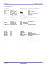
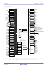
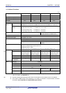
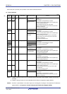
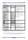
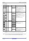
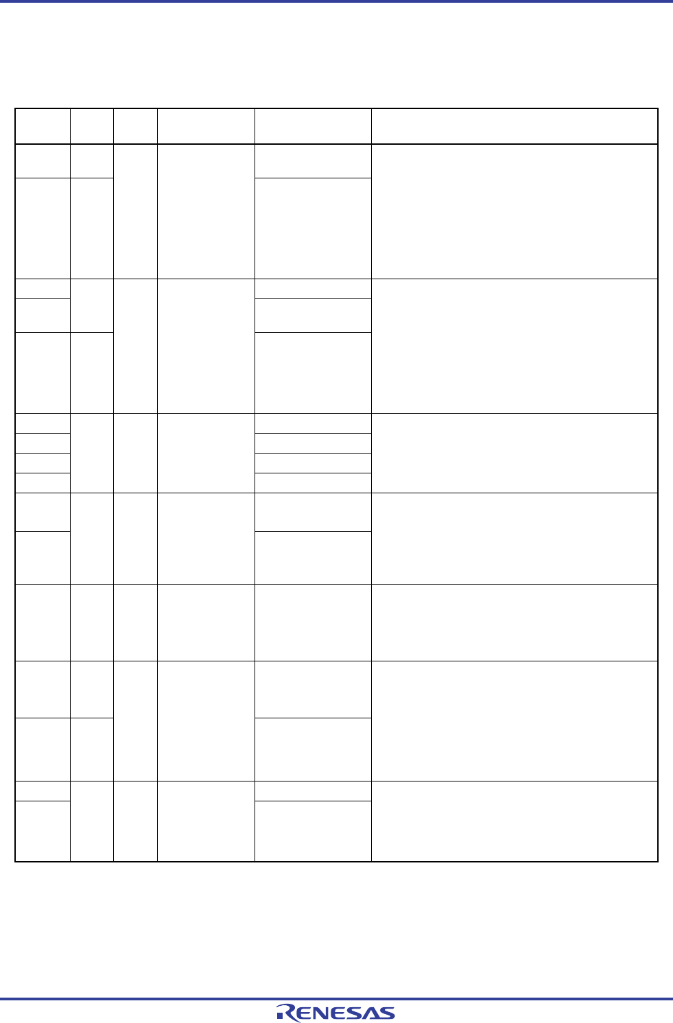
2.1.1 25-pin products
(1/2)
Function
Name
Pin
Type
I/O After Reset Alternate Function Function
P02 7-3-2
ANI17/TI00/TxD1/
(KR0)
P03 8-3-2
I/O Analog input port
ANI16/TO00/RxD1/
(KR1)
Port 0.
2-bit I/O port.
Input/output can be specified in 1-bit units.
Use of an on-chip pull-up resistor can be specified by a
software setting at input port.
Input of P03 can be set to TTL input buffer.
Output of P02 and P03 can be set to N-ch open-drain
output (V
DD tolerance).
Can be set to analog input
Note 1
.
P10
ANI18/SCK00/SCL00
P11
8-3-2
ANI20/SI00/RxD0/
TOOLRxD/SDA00
P12 7-3-2
I/O Analog input port
ANI21/SO00/TxD0/
TOOLTxD
Port 1.
3-bit I/O port.
Input/output can be specified in 1-bit units.
Use of an on-chip pull-up resistor can be specified by a
software setting at input port.
Input of P10 and P11 can be set to TTL input buffer.
Output of P10 to P12 can be set to N-ch open-drain
output (V
DD tolerance).
Can be set to analog input
Note 1
.
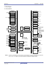
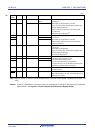
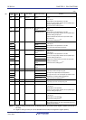
P20 ANI0/AVREFP
P21 ANI1/AVREFM
P22 ANI2/(KR2)
P23
4-3-1 I/O Analog input port
ANI3/(KR3)
Port 2.
4-bit I/O port.
Input/output can be specified in 1-bit units.
Can be set to analog input
Note 2
.
P30 ANI27/INTP3/
SCK11/SCL11
P31
7-3-1 I/O Analog input port
ANI29/TI03/TO03/
INTP4/PCLBUZ0
Port 3.
2-bit I/O port.
Input/output can be specified in 1-bit units.
Use of an on-chip pull-up resistor can be specified by a
software setting at input port.
Can be set to analog input
Note 1
.
P40 7-1-1 I/O Input port TOOL0
Port 4.
1-bit I/O port.
Input/output can be specified.
Use of an on-chip pull-up resistor can be specified by a
software setting at input port.
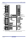
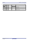
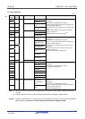
P50 7-3-2 ANI26/INTP1/SI11/
SDA11
P51 7-3-1
I/O Analog input port
ANI25/INTP2/SO11
Port 5.
2-bit I/O port.
Input/output can be specified in 1-bit units.
Use of an on-chip pull-up resistor can be specified by a
software setting at input port.
Output of P50 can be set to N-ch open-drain output
(V
DD tolerance).
Can be set to analog input
Note 1
.
P60
SCLA0
P61
12-1-1 I/O Input port
SDAA0
Port 6.
2-bit I/O port.
Input/output can be specified in 1-bit units.
Output of P60 and P61 can be set to N-ch open-drain
output (6 V tolerance).
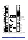
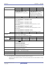
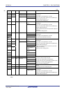
<R>
Notes 1. Digital or analog for each pin can be selected with the port mode control register x (PMCx) (can be set in 1-
bit units).
2. Digital or analog for each pin can be selected with the A/D port configuration register (ADPC).
Remark Functions in parentheses in the above figure can be assigned via settings in the peripheral I/O redirection
register (PIOR). See Figure 4-8 Format of Peripheral I/O Redirection Register (PIOR).
R01UH0305EJ0200 Rev.2.00 20
Jul 04, 2013