


RL78/G1A CHAPTER 12 SERIAL ARRAY UNIT
R01UH0305EJ0200 Rev.2.00 502
Jul 04, 2013
12.6 Operation of UART (UART0 to UART2) Communication
This is a start-stop synchronization function using two lines: serial data transmission (T
XD) and serial data reception
(R
XD) lines. By using these two communication lines, each data frame, which consist of a start bit, data, parity bit, and
stop bit, is transferred asynchronously (using the internal baud rate) between the microcontroller and the other
communication party. Full-duplex UART communication can be performed by using a channel dedicated to transmission
(even-numbered channel) and a channel dedicated to reception (odd-numbered channel). The LIN-bus can be
implemented by using UART2, timer array unit o (channel 0) with an external interrupt (INTP0).
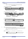
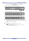
[Data transmission/reception]
• Data length of 7, 8, or 9 bits
Note
• Select the MSB/LSB first
• Level setting of transmit/receive data (selecting whether to reverse the level)
• Parity bit appending and parity check functions
• Stop bit appending, stop bit check function
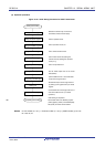
[Interrupt function]
• Transfer end interrupt/buffer empty interrupt
• Error interrupt in case of framing error, parity error, or overrun error
[Error detection flag]
• Framing error, parity error, or overrun error
In addition, UART0 reception (channel 1 of unit 0) supports the SNOOZE mode. When RxD0 pin input is detected while
in the STOP mode, the SNOOZE mode makes data reception that does not require the CPU possible. Only following
UART0 can be specified for the reception baud rate adjustment function.
The LIN-bus is accepted in UART2 (channels 0 and 1 of unit 1) (32, 48, and 64-pin products only).
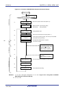
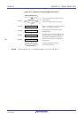
[LIN-bus functions]
• Wakeup signal detection
• Break field (BF) detection
• Sync field measurement, baud rate calculation
Note Only following UART0 can be specified for the 9-bit data length.
Using the external interrupt (INTP0) and
timer array unit 0 (channel 7)
<R>