


RL78/G1A CHAPTER 22 SAFETY FUNCTIONS
<Operation flow>
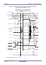
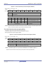
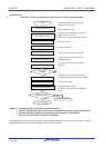
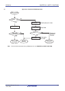
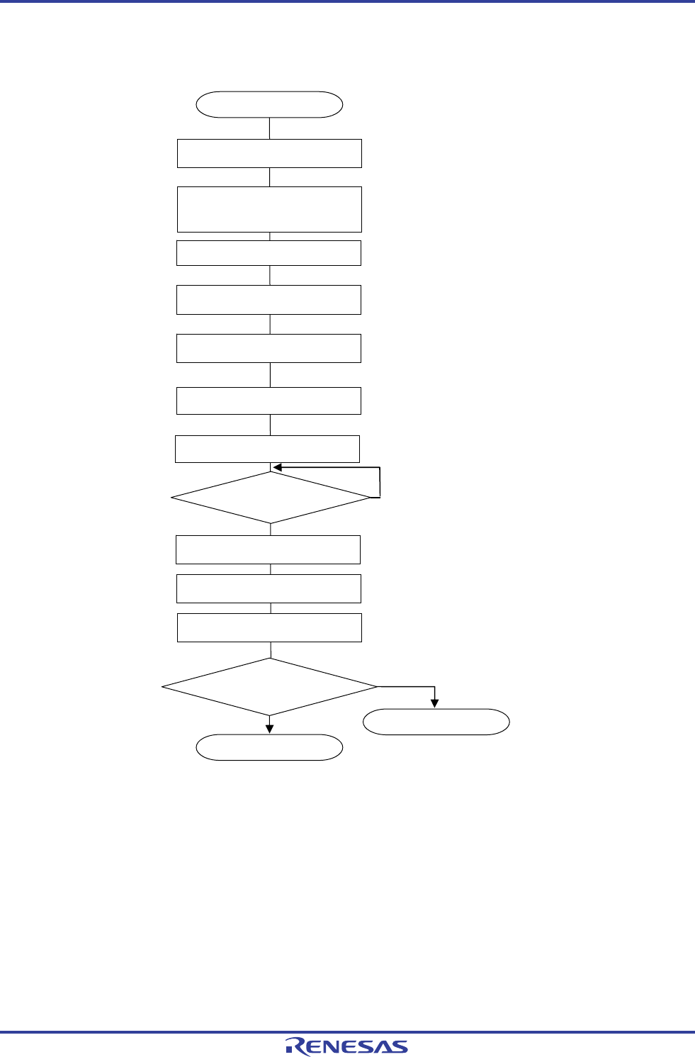
Figure 22-3. Flowchart of Flash Memory CRC Operation Function (High-speed CRC)
<R>
Start
; Store the expected CRC operation result
; value in the lowest 4 bytes.
; Set CRC operation range.
; Copy the HALT and RET instructions to the
; RAM to execute in the RAM.
; Initialize the 10 bytes after the RET instruction.
; Masks all interrupt
; Enable CRC operation
; Initialize the CRC operation result register
; Call the address of the HALT instruction
; copied to the RAM.
; CRC operation starts by HALT instruction
; execution
; When the CRC operation is complete, the HALT
; mode is released and control is returned from RAM
; Prohibit CRC operation
; Read CRC operation result
; Compare the value with the stored expected
; value.
Correctly complete
Abnormal complete
Set FEA5 to FEA0 bits
PGCRCL = 0000H
CRC0EN = 0
Read the value of PGCRCL.
Execute RET instruction.
All xxMKx = 1
Copy HALT and RET instructions to
RAM, initialize 10 bytes
CRC0EN = 1
Compare the value with
the expected CRC value.
Match
Not match
Execute CALL instruction
Execute HALT instruction.
CRC operation
co
m
p
l
eted
?
Yes
No
Cautions 1. The CRC operation is executed only on the code flash.
2. Store the expected CRC operation value in the area below the operation range in the code flash.
3. The CRC operation is enabled by executing the HALT instruction in the RAM area.
Be sure to execute the HALT instruction in RAM area.
The expected CRC value can be calculated by using the Integrated Development Environment CubeSuite+. See the
Integrated Development Environment CubeSuite+ user’s manual for details.
R01UH0305EJ0200 Rev.2.00 775
Jul 04, 2013