


RL78/G1A CHAPTER 12 SERIAL ARRAY UNIT
R01UH0305EJ0200 Rev.2.00 447
Jul 04, 2013
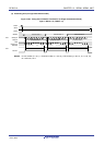
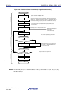
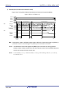
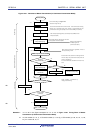
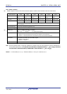
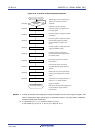
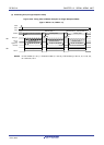
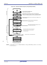
12.5.2 Master reception
Master reception is that the RL78 microcontroller outputs a transfer clock and receives data from other device.
3-Wire Serial I/O CSI00 CSI01 CSI10 CSI11 CSI20 CSI21
Target channel Channel 0 of
SAU0
Channel 1 of
SAU0
Channel 2 of
SAU0
Channel 3 of
SAU0
Channel 0 of
SAU1
Channel 1 of
SAU1
Pins used SCK00, SI00 SCK01, SI01 SCK10, SI10 SCK11, SI11 SCK20, SI20 SCK21, SI21
INTCSI00 INTCSI01 INTCSI10 INTCSI11 INTCSI20 INTCSI21 Interrupt
Transfer end interrupt (in single-transfer mode) or buffer empty interrupt (in continuous transfer mode)
can be selected.
Error detection flag Overrun error detection flag (OVFmn) only
Transfer data length 7 or 8 bits
Transfer rate
Note
Max. fCLK/2 [MHz] (CSI00 only), fCLK/4 [MHz]
Min. f
CLK/(2 × 2
15
× 128) [Hz]
Note
fCLK: System clock frequency
Data phase Selectable by the DAPmn bit of the SCRmn register
• DAPmn = 0: Data input starts from the start of the operation of the serial clock.
• DAPmn = 1: Data input starts half a clock before the start of the serial clock operation.
Clock phase Selectable by the CKPmn bit of the SCRmn register
• CKPmn = 0: Non-reverse
• CKPmn = 1: Reverse
Data direction MSB or LSB first
Note Use this operation within a range that satisfies the conditions above and the peripheral functions characteristic in
the electrical specifications (see CHAPTER 29 ELECTRICAL SPECIFICATIONS (T
A = −40 to +85°C), CHAPTER
30 ELECTRICAL SPECIFICATIONS (G: INDUSTRIAL APPLICATIONS TA = −40 to +105°C)).
Remark m: Unit number (m = 0, 1), n: Channel number (n = 0 to 3), mn = 00 to 03, 10, 11
<R>
<R>