


RL78/G1A CHAPTER 5 CLOCK GENERATOR
R01UH0305EJ0200 Rev.2.00 176
Jul 04, 2013
5.6.6 Time required for switchover of CPU clock and system clock
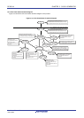
By setting bits 4 and 6 (MCM0, CSS) of the system clock control register (CKC), the CPU clock can be switched
(between the main system clock and the subsystem clock), and main system clock can be switched (between the high-
speed on-chip oscillator clock and the high-speed system clock).
The actual switchover operation is not performed immediately after rewriting to the CKC register; operation continues
on the pre-switchover clock for several clocks (see Table 5-5 to Table 5-7).
Whether the CPU is operating on the main system clock or the subsystem clock can be ascertained using bit 7 (CLS) of
the CKC register. Whether the main system clock is operating on the high-speed system clock or high-speed on-chip
oscillator clock can be ascertained using bit 5 (MCS) of the CKC register.
When the CPU clock is switched, the peripheral hardware clock is also switched.
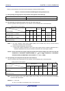
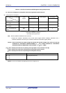
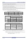
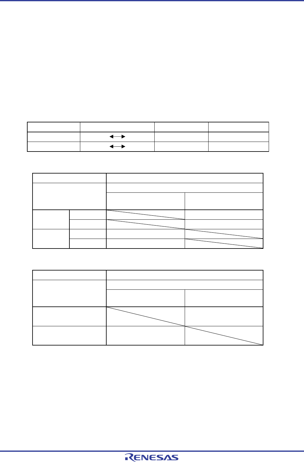
Table 5-5. Maximum Time Required for System Clock Switchover
Clock A Switching directions Clock B Remark
fIH fMX See Table 5-6
fMAIN fSUB See Table 5-7
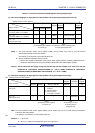
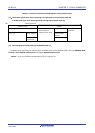
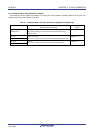
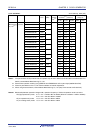
Table 5-6. Maximum Number of Clocks Required for f
IH ↔ fMX
Set Value Before Switchover Set Value After Switchover
MCM0 MCM0
0
(f
MAIN = fIH)
1
(fMAIN = fMX)
fMX≥fIH 2 clock
0
(f
MAIN = fIH)
f
MX<fIH 2fIH/fMX clock
fMX≥fIH 2fMX/fIH clock
1
(f
MAIN = fMX)
f
MX<fIH 2 clock
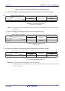
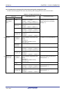
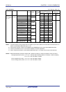
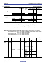
Table 5-7. Maximum Number of Clocks Required for f
MAIN ↔ fSUB
Set Value Before Switchover Set Value After Switchover
CSS CSS
0
(f
CLK = fMAIN)
1
(fCLK = fSUB)
0
(f
CLK = fMAIN)
1 + 2f
MAIN/fSUB clock
1
(f
CLK = fSUB)
3 clock
Remarks 1. The number of clocks listed in Table 5-6 and Table 5-7 is the number of CPU clocks before switchover.
2. Calculate the number of clocks in Table 5-6 and Table 5-7 by removing the decimal portion.
Example When switching the main system clock from the high-speed system clock to the high-speed on-
chip oscillator clock (@ oscillation with f
IH = 8 MHz, fMX = 10 MHz)
2f
MX/fIH = 2 (10/8) = 2.5 → 3 clocks