RL78/G1A CHAPTER 11 A/D CONVERTER
R01UH0305EJ0200 Rev.2.00 349
Jul 04, 2013
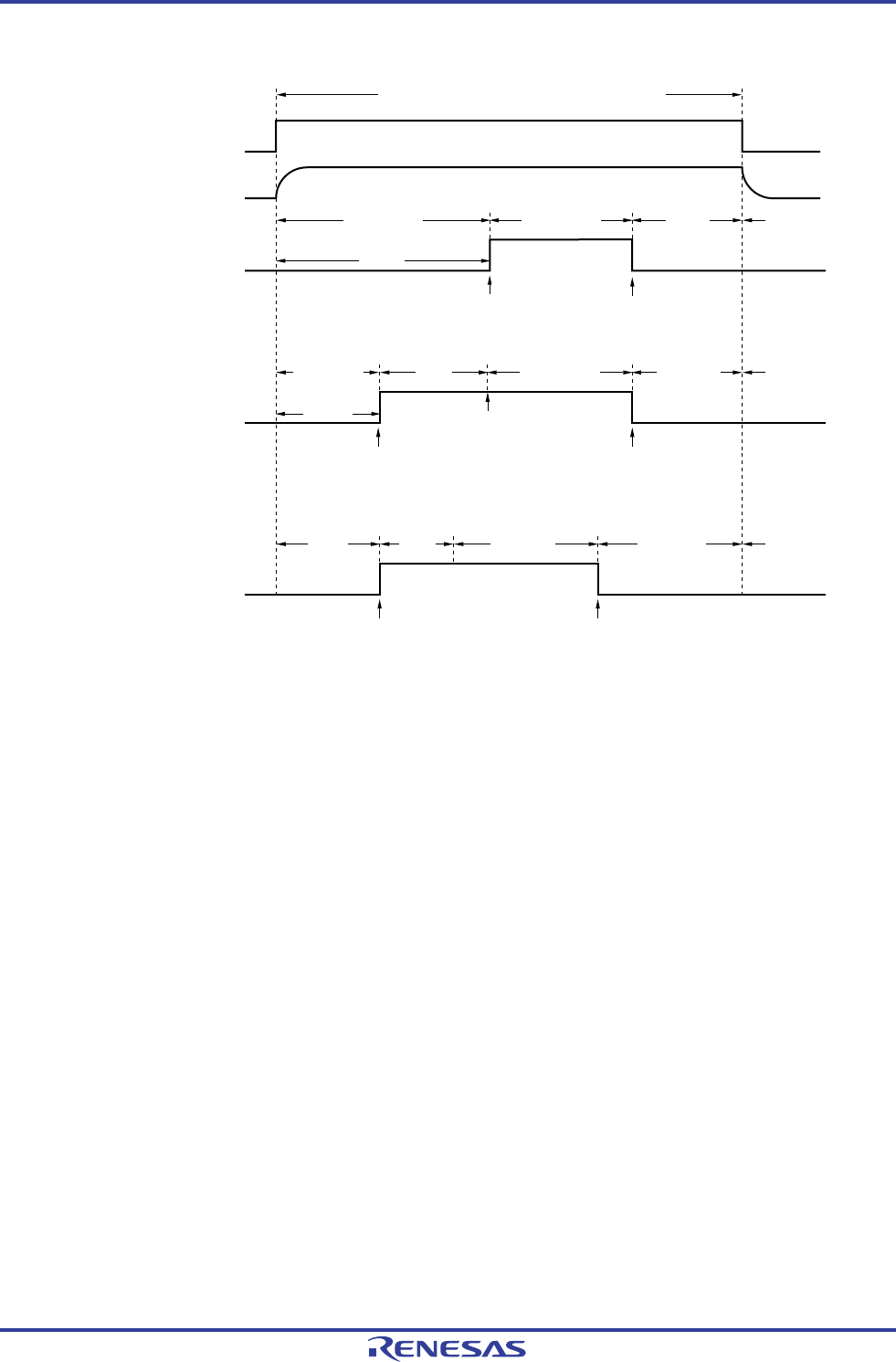
Figure 11-4. Timing Chart When A/D Voltage Comparator Is Used
ADCE
A/D voltage comparator
Software
trigger mode
ADCS
Conversion
stopped
Conversion
standby
1 is written
to ADCS.
0 is written
to ADCS.
Conversion
standby
A/D voltage comparator: enables operation
Note 1
Note 1
Hardware trigger
no-wait mode
Conversion
operation
ADCS
Conversion
stopped
Conversion
standby
Trigger
standby
1 is written
to ADCS.
After detection
hardware trigger
0 is written
to ADCS.
Conversion
standby
Conversion
operation
Hardware trigger
wait mode
ADCS
Conversion
stopped
Conversion
standby,
trigger
standby
After detiction
hardware trigger
0 is written
to ADCS.
Conversion
standby,
trigger
standby
Conversion
operation
A/D power
supply
stabilization
wait time
Note 2
Notes 1. While in the software trigger mode or hardware trigger no-wait mode, the time from the rising of the ADCE
bit to the falling of the ADCS bit must be following time or longer to stabilize the internal circuit.
[Stabilization wait status]
If a high-accuracy channel is selected as the analog input channel: 0.5
μ
s
If a test mode setting (ADTES1 bit of ADTES register = 1) is selected: 0.5
μ
s
If a standard channel is selected as the analog input channel: 2
μ
s
If a temperature sensor output/internal reference voltage output are selected as the analog input channel:
(ADISS bit of ADS register = 1): 2
μ
s
2. For the second and subsequent conversion in sequential conversion mode and for conversion of the
channel specified by scan 1, 2, and 3 in scan mode, the A/D power supply stabilization wait time do not
occur after a hardware trigger is detected.
Cautions 1. If using the hardware trigger wait mode, setting the ADCS bit to 1 is prohibited (but the bit is
automatically switched to 1 when the hardware trigger signal is detected). However, it is possible
to clear the ADCS bit to 0 to specify the A/D conversion standby status.
2. While in the one-shot conversion mode of the hardware trigger no-wait mode, the ADCS flag is
not automatically cleared to 0 when A/D conversion ends. Instead, 1 is retained.
3 Only rewrite the value of the ADCE bit when ADCS = 0 (while in the conversion
stopped/conversion standby status).
4. To complete A/D conversion, specify at least the following time as the hardware trigger interval:
Hardware trigger no wait mode: 2 f
CLK clock + A/D conversion time
Hardware trigger wait mode: 2 f
CLK clock + A/D power supply stabilization wait time +
A/D conversion time
Remark f
CLK: CPU/peripheral hardware clock frequency
<R>


