


RL78/G1A CHAPTER 5 CLOCK GENERATOR
R01UH0305EJ0200 Rev.2.00 143
Jul 04, 2013
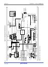
Remark fX: X1 clock oscillation frequency
fIH: High-speed on-chip oscillator clock frequency
f
EX: External main system clock frequency
f
MX: High-speed system clock frequency
fMAIN: Main system clock frequency
f
XT: XT1 clock oscillation frequency
f
EXS: External subsystem clock frequency
fSUB: Subsystem clock frequency
f
CLK: CPU/peripheral hardware clock frequency
f
IL: Low-speed on-chip oscillator clock frequency
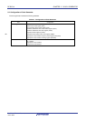
5.3 Registers Controlling Clock Generator
The following nine registers are used to control the clock generator.
• Clock operation mode control register (CMC)
• System clock control register (CKC)
• Clock operation status control register (CSC)
• Oscillation stabilization time counter status register (OSTC)
• Oscillation stabilization time select register (OSTS)
• Peripheral enable register 0 (PER0)
• Subsystem clock supply mode control register (OSMC)
• High-speed on-chip oscillator frequency select register (HOCODIV)
• High-speed on-chip oscillator trimming register (HIOTRM)
Caution Which registers and bits are included depends on the product. Be sure to set registers and bits that
are not mounted in a product to their initial values.
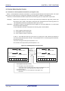
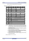
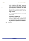
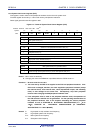
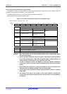
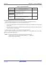
5.3.1 Clock operation mode control register (CMC)
This register is used to set the operation mode of the X1/P121, X2/EXCLK/P122, XT1/P123, and XT2/EXCLKS/P124
pins, and to select a gain of the oscillator.
The CMC register can be written only once by an 8-bit memory manipulation instruction after reset release. This
register can be read by an 8-bit memory manipulation instruction.
Reset signal generation clears this register to 00H.
<R>
<R>