


RL78/G1A CHAPTER 6 TIMER ARRAY UNIT
R01UH0305EJ0200 Rev.2.00 187
Jul 04, 2013
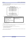
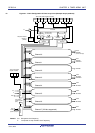
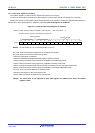
6.1.4 LIN-bus supporting function (channel 7 of unit 0 only)
Timer array unit is used to check whether signals received in LIN-bus communication match the LIN-bus
communication format.
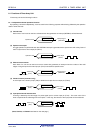
(1) Detection of wakeup signal
The timer starts counting at the falling edge of a signal input to the serial data input pin (RxD2) of UART2 and the
count value of the timer is captured at the rising edge. In this way, a low-level width can be measured. If the low-
level width is greater than a specific value, it is recognized as a wakeup signal.
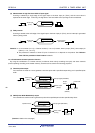
(2) Detection of break field
The timer starts counting at the falling edge of a signal input to the serial data input pin (RxD2) of UART2 after a
wakeup signal is detected, and the count value of the timer is captured at the rising edge. In this way, a low-level
width is measured. If the low-level width is greater than a specific value, it is recognized as a break field.
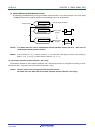
(3) Measurement of pulse width of sync field
After a break field is detected, the low-level width and high-level width of the signal input to the serial data input pin
(RxD2) of UART2 are measured. From the bit interval of the sync field measured in this way, a baud rate is
calculated.
Remark For details about setting up the operations used to implement the LIN-bus, see 6.3.13 Input switch control
register (ISC) and 6.8.5 Operation as input signal high-/low-level width measurement.