


RL78/G1A CHAPTER 8 INTERVAL TIMER
8.3 Registers Controlling 12-bit Interval Timer
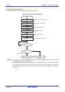
The 12-bit interval timer is controlled by the following registers.
• Peripheral enable register 0 (PER0)
• Subsystem clock supply mode control register (OSMC)
• Interval timer control register (ITMC)
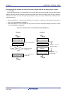
8.3.1 Peripheral enable register 0 (PER0)
This register is used to enable or disable supplying the clock to the peripheral hardware. Clock supply to a hardware
macro that is not used is stopped in order to reduce the power consumption and noise.
When the 12-bit interval timer is used, be sure to set bit 7 (RTCEN) of this register to 1.
The PER0 register can be set by a 1-bit or 8-bit memory manipulation instruction.
Reset signal generation clears this register to 00H.
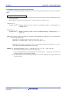
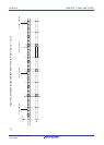
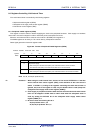
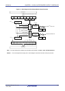
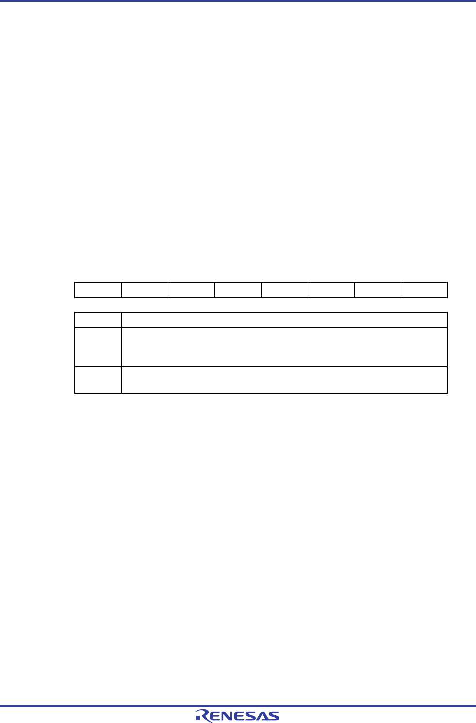
Figure 8-2. Format of Peripheral Enable Register 0 (PER0)
Address: F00F0H After reset: 00H R/W
Symbol <7> 6 <5> <4> <3> <2> 1 <0>
PER0 RTCEN 0 ADCEN IICA0EN SAU1EN
Note
SAU0EN 0 TAU0EN
RTCEN Control of real-time clock (RTC) and 12-bit interval timer input clock supply
0
Stops clock supply.
• SFR used by the real-time clock (RTC) and 12-bit interval timer cannot be written.
• The real-time clock (RTC) and 12-bit interval timer are in the reset status.
1
Enables clock supply.
• SFR used by the real-time clock (RTC) and 12-bit interval timer can be read and written.
Note 32, 48, and 64-pin products only.
Cautions 1. When using the 12-bit interval timer, be sure to first set the RTCEN bit to 1 and then
set the interval timer control register (ITMC), while oscillation of the count clock is
stable. If RTCEN = 0, writing to the registers controlling the 12-bit interval timer is
ignored, and, even if the register is read, only the default value is read (except the
subsystem clock supply mode control register (OSMC)).
<R>
2. Clock supply to peripheral functions other than the real-time clock and 12-bit interval
timer can be stopped in STOP mode or HALT mode when the subsystem clock is
used, by setting the RTCLPC bit of the subsystem clock supply mode control
register (OSMC) to 1.
3. Be sure to clear the following bits to 0.
25-pin products: bits 1, 3, 6
32, 48, 64-pin products: bits 1, 6
R01UH0305EJ0200 Rev.2.00 322
Jul 04, 2013