


RL78/G1A CHAPTER 12 SERIAL ARRAY UNIT
R01UH0305EJ0200 Rev.2.00 539
Jul 04, 2013
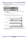
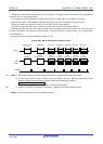
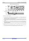
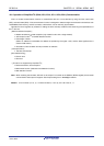
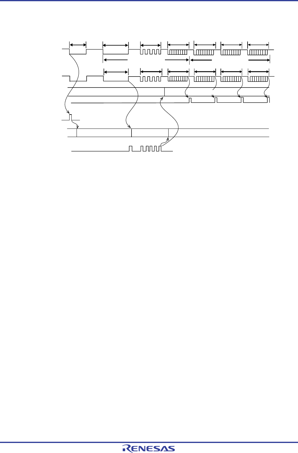
Figure 12-99. Reception Operation of LIN
LIN Bus
RxD2
TM07
INTTM07
UART2
INTSR2
Checksum
field
Data filed
Data filed
Identification
field
Sync field
Break field
Wakeup signal
frame
Message header
BF reception
SF
reception
ID
reception
Data
reception
Edge detection
(INTP0)
<1>
<2>
<3>
<4>
<5>
STOP
Pulse interval measurement
Pulse width measurement
Pulse width measurement
STOP
Message
Reception stop
Data
reception
Data
reception
Here is the flow of reception processing.
<1> The wakeup signal is detected by detecting an interrupt edge (INTP0) on a pin. When the wakeup signal is
detected, change TM07 to pulse width measurement upon detection of the wakeup signal to measure the low-
level width of the BF signal. Then wait for BF signal reception.
<2> TM07 starts measuring the low-level width upon detection of the falling edge of the BF signal, and then captures
the data upon detection of the rising edge of the BF signal. The captured data is used to judge whether it is the
BF signal.
<3> When the BF signal has been received normally, change TM07 to pulse interval measurement and measure the
interval between the falling edges of the RxD2 signal in the sync field four times (see 6.8.4 Operation as input
pulse interval measurement).
<4> Calculate a baud rate error from the bit interval of sync field (SF). Stop UART2 once and adjust (re-set) the baud
rate.
<5> The checksum field should be distinguished by software. In addition, processing to initialize UART2 after the
checksum field is received and to wait for reception of BF should also be performed by software.