


RL78/G1A CHAPTER 13 SERIAL INTERFACE IICA
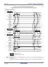
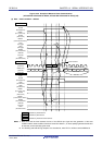
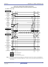
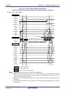
The meanings of <7> to <15> in (3) Data ~ data ~ stop condition in Figure 13-32 are explained below.
<7> After data transfer is completed, because of ACKE0 = 1, the slave device sends an ACK by hardware to the
master device. The ACK is detected by the master device (ACKD0 = 1) at the rising edge of the 9th clock.
<8> The master device and slave device set a wait status (SCLA0 = 0) at the falling edge of the 9th clock, and
both the master device and slave device issue an interrupt (INTIICA0: end of transfer).
<9> The master device writes the data to transmit to the IICA shift register 0 (IICA0) and releases the wait
status that it set by the master device.
<10> The slave device reads the received data and releases the wait status (WREL0 = 1). The master device
then starts transferring data to the slave device.
<11> When data transfer is complete, the slave device (ACKE0 =1) sends an ACK by hardware to the master
device. The ACK is detected by the master device (ACKD0 = 1) at the rising edge of the 9th clock.
<12> The master device and slave device set a wait status (SCLA0 = 0) at the falling edge of the 9th clock, and
both the master device and slave device issue an interrupt (INTIICA0: end of transfer).
<13> The slave device reads the received data and releases the wait status (WREL0 = 1).
<14> By the master device setting a stop condition trigger (SPT0 = 1), the bus data line is cleared (SDAA0 = 0)
and the bus clock line is set (SCLA0 = 1). After the stop condition setup time has elapsed, by setting the
bus data line (SDAA0 = 1), the stop condition is then generated (i.e. SCLA0 =1 changes SDAA0 from 0 to
1).
<15> When a stop condition is generated, the slave device detects the stop condition and issues an interrupt
(INTIICA0: stop condition).
Remark <1> to <15> in Figure 13-32 represent the entire procedure for communicating data using the I
2
C bus.
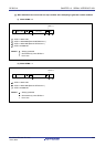
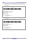
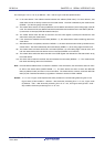
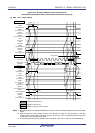
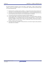
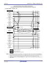
Figure 13-32 (1) Start condition ~ address ~ data shows the processing from <1> to <6>, Figure 13-32
(2) Address ~ data ~ data shows the processing from <3> to <10>, and Figure 13-32 (3) Data ~ data ~
stop condition shows the processing from <7> to <15>.
R01UH0305EJ0200 Rev.2.00 643
Jul 04, 2013