


76 Chapter 1 Introduction to the Business Communications Manager Platform Hardware
P0993133 03
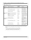
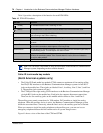
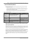
Table 10 provides a description of the function for each DTM LEDs.
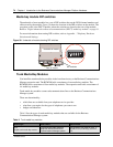
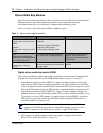
Caller ID trunk media bay module
(North American systems only)
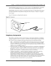
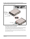
• The Caller ID Trunk media bay module (CTM) connects a maximum of four analog calling
line ID (CLID) interfaces to the Business Communications Manager system via four RJ11
jacks on the module face. These jacks are labeled: Line 1, Auxiliary, Line 2, Line 3, and Line
4. The auxiliary jack connects to Line 1.
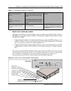
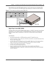
• The CTM8 provides eight analog CLID interfaces to the Business Communications Manager
via eight RJ11 jacks on the module face. Each jacks also supports disconnect supervision.
There are also two auxiliary jacks on this module which connect to Line 1 and Line 5.
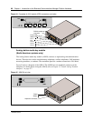
The auxiliary ports permit connection of a V.90 modem, FAX machine or single line analog
telephone. When the auxiliary device is active, the Business Communications Manager system
blocks the associated line. Conversely, when the line is active, the auxiliary port line is blocked.
When you connect a single line analog telephone to the auxiliary port, you can use it as an
emergency telephone because this line remains active if a power outage occurs.
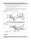
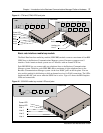
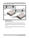
Figure 41 shows a view of the front of the CTM and CTM8.
Table 10 DTM LED functions
LED label Function
(Power) On indicates that the DTM is receiving +5 volts.
(Status) On indicates there is data communication between the DTM and the MSC card.
In Service Flashing indicates that the T1, ETSI or PRI trunks are out of service because a loopback
test is running or the DTM is initializing.
Loopback On indicates a continuity loopback test is running.
Receive Alarm On indicates a problem with the received digital transmission. This half-duplex link does
not work.
Receive Error On indicates a small error as a result of degraded digital transmission. Possible causes
are an ohmic connection, water ingress, or too long a loop.
Transmit Alarm On indicates the DTM cannot transmit. The DTM sends an Alarm indication signal (AIS) to
the terminating switch. This half-duplex link does not work.
Transmit Error On indicates the DTM is sending a remote alarm indication (RAI) carrier failure alarm
(CFA) to the terminating switch. If the Transmit Alarm is not on, this error indicates a
far-end or cable problem.
All LEDS flashing All LEDs flashing continuously indicates that the DTM is initializing.
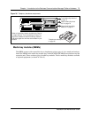
TIP: You can install a maximum of three DTM modules in the Business Communications
Manager system, depending on the available channels.