


Chapter 9 Replace or Upgrade a Power Supply 197
Installation and Maintenance Guide
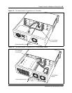
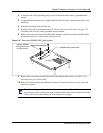
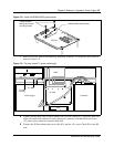
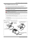
Figure 124 Install the BCM200 MSC guide bracket
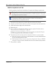
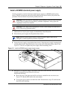
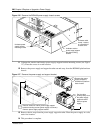
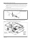
7 Install a P1 power cable to the media bay backplane connector. Tie-wrap the excess cable as
shown in Figure 125.
Figure 125 Tie-wrap excess P1 power cable length
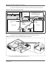
8 Connect the hard disk cable to the secondary IDE I/O card connection. Connect the hard disk
cable to the hard disk connector. Connect the power connector to the hard disk (see Figure
125). Insert extra connectors under the hard disk
9 Connect the 20 Pin motherboard power cable (P1) and the +12v power Cable (P9) to the I/O
card.
Fasten BCM200
MSC guide bracket
mounting screws
BCM200 MSC guide bracket
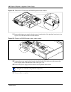
I/O Card
Hard disk
Fan
MSC
Media bay module backplane
I/O card
Power supply
P1 cable
P1 cable
tie-wrap