


Chapter 1 Introduction to the Business Communications Manager Platform Hardware 65
Installation and Maintenance Guide
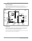
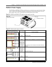
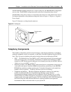
Platform Power Supply
The BCM200 and BCM400 (STD) base platforms use a switched power supply. Internal cabling
routes to the I/O card, media bay backplane and hard disk. External cabling extends to the line
power supply outlet. Figure 28 illustrates the standard platform power supply.
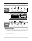
Figure 28 BCM200 and BCM400 (STD) platform power supply (rear view)
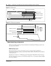
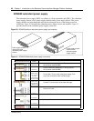
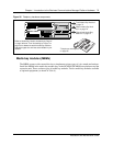
Figure 29 Standard power supply connectors
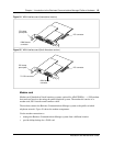
Rear view:
Standard power supply
Fan
AC power connector
On/Off switch
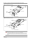
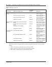
Connector Configuration for
Standard Sparkle Power Supply New Lengths
Purpose and Notes
500mm to first,
+50mm to next,
+100mm to last
(total 650mm)
tie wrapped
every 5cm
480mm
430mm to first
(right angle) ,
+150mm to
next (total
580mm)
525mm MBM Back plane
MBM Back plane for BCM400, not required for BCM200
Hard disk cage, extra connectors to be tucked under the
hard disk
Reserved for future use
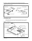
I/O Card
I/O Card
525mm
480mm