


Telephony Hardware Selection and Settings 329
Installation and Maintenance Guide
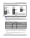
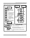
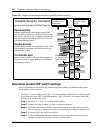
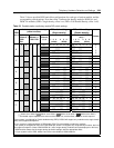
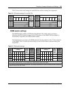
Table 53 shows possible DS30 and offset configurations for each type of station module, and the
corresponding switch settings. Note that offset 1 indicates the density mode for DSM 16+ and
DSM 32+ modules (SDD = single density, offset 1:on; FDD = Full Double Density, offset 1:off).
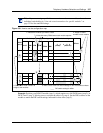
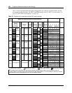
Table 53 Possible station media bay module DIP switch settings
DS30
bus #
Media bay module positioning
(station modules)
DIP switch settings
(Single density)
DIP switch settings
(Double density)
Offsets
DSM 16+
Offsets 0, 1
SDD
FDD
DSM 32+
Offsets 0, 1
SDD FDD
ASM 8
Offsets 0,
1, 2, 3
12 3 456
(offset) (DS30)
DSM 16+ and DSM 32+
only***
12 3 456
(offset) (DS30)
2
0 0 0 0 0*** on on on on on on off on on on on on
0
1 on on off on on on off on off on on on
1
1 2 on off on on on on off off on on on on
2
3 on off off on on on off off off on on on
3
3
0 0 0 0 0 on on on on on off off on on on on off
0
1 on on off on on off off on off on on off
1
1 2 on off on on on off off off on on on off
2
3 on off off on on off off off off on on off
3
4
0 0 0 0 0 on on on on off on off on on on off on
0
1 on on off on off on off on off on off on
1
1 2 on off on on off on off off on on off on
2
3 on off off on off on off off off on off on
3
5
0 0 0 0 0 on on on on off off off on on on off off
0
1 on on off on off off off on off on off off
1
1 2 on off on on off off off off on on off off
2
3 on off off on off off off off off on off off
3
6*
0 0 0 0 0 on on on off on on off on on off on on
0
1 on on off off on on off on off off on on
1
1 2**** on off on off on on off off on off on on
2
3*** on off off off on on off off off off on on
3
7**
0 0 0 0 on on on off on off off on on off on off
0
1 on on off off on off off on off off on off
1
1 2**** on off on off on off off off on off on off
2
3*** on off off off on off off off off off on off
3
Module set to offset 0 Module set to offset 1 Module set to offset 2 Module set to offset 3
Each shaded square represents the amount of the DS30 bus, and the offset, which the module requires.
*If your system is configured for Partial double density (PDD), DS30 6 will support only modules set to single density
(SDD) and it supports Companion.
**If your system is configured with a 3/5 DS30 split, DS30 7 is not available to media bay modules.
If your system is configured for PDD and a 2/6 DS30 split, DS30 7 will support only single-density modules, but it will
also support Companion. (Note: DSM 32/DSM 32+ (set to single density) modules cannot be deployed on this bus.)
***ASM modules always use the single density dip switch settings, with the appropriate offset.
****If your system is set to PDD, offsets 2 and 3 are not available to ASM8 modules.