


204 Chapter 9 Replace or Upgrade a Power Supply
P0993133 03
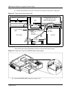
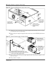
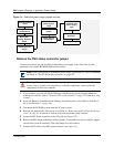
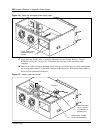
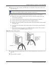
Figure 131 Redundant power supply upgrade overview
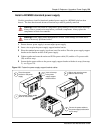
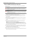
Remove the PSU status connector jumper
Use this procedure if you are installing a redundant power supply for the first time. Use this
procedure only with the BCM400 platform base chassis.
1 If you still have access to the Unified Manager, shut down the system using the Shutdown
command. For details, refer to “Shut down the system software” on page 145. Otherwise, skip
to step 2.
2 Set up the Business Communications Manager for maintenance, as described in “Shut down
the system hardware” on page 146.
3 Disconnect the BCM400 system from the AC power outlet.
4 Remove the platform base chassis top cover. Refer to “Remove the platform base chassis top
cover” on page 161. Continue to the next step in this procedure when complete.
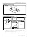
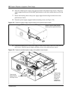
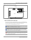
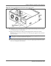
5 Locate the PSU Status connector on the I/O card (see Figure 132).
6 Remove the RPS output signaling connector jumper. Use needle-nose pliers to pull the jumper
out and away from the connector. Place the jumper in a safe location.
7 Connect the PA cable to the PSU status connector (see Figure 31).
Note: When you upgrade to a redundant power supply, you should also install a redundant
fan. Refer to “Install a BCM400 cooling fan” on page 182.
Warning: Protect the hardware components against damage from electrostatic discharge.
Always wear a ground wrist strap before you handle components. Always place the
components in static-free container.
Shut the system
down
Install redundant
power supply
cage
Remove PSU
jumper
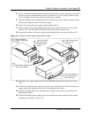
Insert both
modules into
power supply
cage
Restore unit to
operation
Check power LED
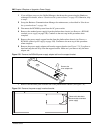
Note cable
routing. Remove
cables
Remove the
standard power
supply
Make internal
connections
Set up unit for
maintenance