


322 Telephony Hardware Selection and Settings
P0993133 03
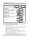
Set Media Bay Module Dip Switches
Before you install a media bay module, assign switch settings for the media bay module. These
settings determine which line numbers (trunks) or DNs (extensions) the equipment connected to
the module will have access to. The DIP switches are located on the back or underside of the
media bay module.
Start from the list of modules you chose in Chapter 4, “Install, remove or replace the Media Bay
Modules,” on page 109.
After you determine which DS30 buses you want to use, and how much DS30 capacity each
module requires, determine the location of the modules on the DS30 array. From that information,
you choose switch settings for each module. These settings are then set on the module DIP
switches.
This chapter describes the latter process of positioning your modules in the DS30 hierarchy and
determining and setting the DIP switch settings on the module.
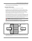
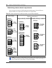
Rules for Assigning DS30 Resources
Media bay modules are assigned to DS30 buses in a specific hierarchical manner. This section
describes the preferred order of positioning for each type of module.
Notes about assigning modules
The following are some general notes about assigning modules:
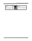
• The DIP switches on the DDIM module are used to set the DS30 designation for the DTM part
of the module. The module automatically assigns an additional DS30 for the data module part
of the DDIM. You cannot choose DS30 7 for the DDIM module, because the data module
would not be accessible. The same applies to DS30 6 if your system is set to a 3/5 split. Refer
to DDIM switch settings on page DDIM switch settings on page 333.
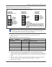
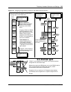
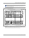
• If you chose a 3/5 channel split for your system, DS30 7 cannot be used by any module. For
modules that require two buses, this means that you cannot set the DIP switches to DS30 6 for
those modules, because the second level of lines would fall into DS30 7, which would not be
accessible. Refer to Figure 197 on page 325.
Refer to “Understanding DS30 numbers” on page 84 for more information about 2/6 and 3/5
DS30 channel splits.
Note: Fiber Expansion Module (FEM) switches
The switches on the fiber expansion module (FEM) do not work in the same way as those
on the other media bay modules. On the FEM, the switches turn the fiber ports on and off.
For information about setting the switches on an FEM, refer to “FEM switch settings” on
page 344.