


218 Chapter 10 Replace Data Cards and Processing Hardware
P0993133 03
•
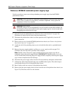
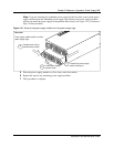
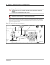
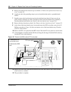
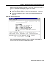
Figure 144 shows an interior view of the base function tray (looking forward). The illustration
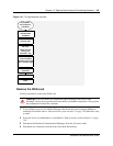
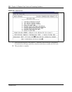
identifies the location of interior components and chassis features. Use the flow chart shown in
Figure 145 to replace the cards.
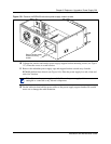
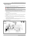
Figure 144 Base function tray interior components
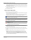
Danger: Electrical shock warning.
Disconnect the power cord, telephone cables and network cables before opening the
computer.
Read and follow installation instructions carefully.
Caution: Use only a Nortel Networks approved replacement. Contact your account
representative for the current list of approved replacement parts.
PCI cover screw
Base function tray face
PCI cover plate
PCI Riser
card
connectors
Main card
WAN slot MSC slot
Modem
card
Modem card
interface