


Chapter 1 Introduction to the Business Communications Manager Platform Hardware 69
Installation and Maintenance Guide
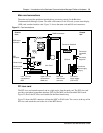
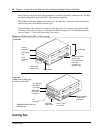
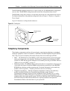
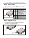
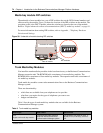
The BCM200/400 standard platforms use a single cooling fan. The BCM400 RFO configuration
uses two fans. The BCM200 cooling fan mounts on the rear of the platform base chassis.
The BCM400 cooling fan(s) mount on a removable panel at the rear of the platform base chassis.
For further information on the platform cooling fans, refer to Chapter 9, “Replace or Upgrade a
Power Supply’.
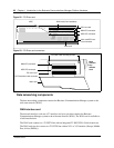
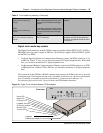
Figure 35 illustrates a cooling fan and connectors.
Figure 35 Cooling fan
Telephony Components
The telephony components perform call processing by connecting the telephones or peripheral
telephony equipment, such as fax machines, to the Public Switched Telephone Network (PSTN)
lines. They also process telephony information that has been received through an IP link.
• MSC — The Media Services Card (MSC) is a PCI card which performs call processing and
media processing of the voice channels. The Business Communications Manager 3.0 MSC
contains two PEC IIIs that provide additional voice channel processing for the MSC. Refer to
“Media services card (MSC)” on page 57.
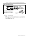
• Media bay modules: The MBMs connect with external devices to implement various types of
voice trunks and stations. Install the MBMs in the media bay module bays in the BCM200,
BCM400 base platforms and the expansion unit. For further information on the media bay
modules, refer to Appendix , “Telephony Hardware Selection and Settings.
• Telephones and adapters — Business telephones and adapters connect to the media bay
modules installed in the Business Communications Manager system. Business
Communications Manager supports Norstar and Business Series Terminal sets, as well as
IP-based Nortel sets. Refer to Telephones and adapters on page 85 for a description of the
telephones that can be used with the system. The Nortel Networks i2002, i2004 IP telephones
and Nortel Networks i2050 Software Phone have separate installation and operations
documentation. Refer to the main index on your system CD.
I/O card fan
connector
Chassis mount
holes