


Chapter 1 Introduction to the Business Communications Manager Platform Hardware 73
Installation and Maintenance Guide
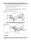
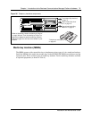
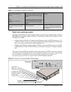
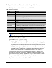
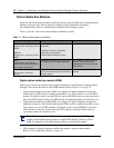
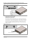
Media bay module LED indicators
Figure 37 shows the location of the (Power) and (Status) on a CTM. The power and status
LEDs are located in the same place on all modules. The figure describes the possible LED states.
Figure 37 Module Power and Status LED states
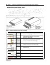
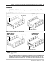
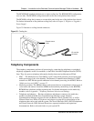
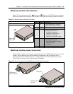
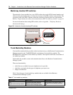
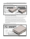
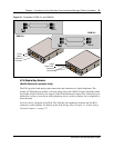
Media bay module power connections
The back of the modules have a single connector that provides a DS256 channel and power to the
module. These connectors plug into the media bay backplane on the base function tray or
expansion unit. Some modules also have a cooling fan that runs off the module power source.
Figure 38 shows the rear views of the two types of modules.
Figure 38 Rear of modules showing DS256 channel and power connectors
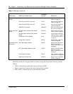
Power Status Description
Off Off No power applied to the module, or
failure of module power converter.
On Off FPGA not downloaded.
On Blinking Hardware is working, but there is an
operational problem such as:
• no DS256 link detected
• DS256 frame alignment lost
• bandwidth not allocated
• module is in maintenance state
Blinking Blinking Power is applied to module, but there is a
hardware problem such as:
• partial failure of power converter
• thermal overload
• fan failure
On On The module is read to operate.
CTM
Power LED
Status LED
DS256 and power
connector
DS256 and
power connector
Cooling fan