


Chapter 9 Replace or Upgrade a Power Supply 207
Installation and Maintenance Guide
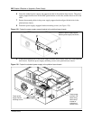
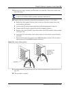
8 Remove both power supply modules from the redundant power supply cage before you install
the power supply in the platform base chassis (see Remove a power supply module on page
214). Continue to the next step of this procedure when complete.
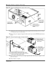
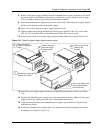
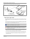
9 Place the redundant power supply (top down) on a flat surface. Place the power supply support
bracket on the bottom surface of the power supply.
10 Insert a tie-wrap in the power supply support bracket lanclet.
11 Gather together and route the Motherboard 20 Pin power cable (P1) the +12v power cable
(P9), the 3.3v load cable (PB), and the PS monitor Cable (PA) to the tie-wrap.
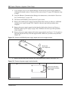
12 Secure the the cables to the power supply support bracket with a tie-wrap (see Figure 128).
Figure 135 Fasten the power supply support bracket cables
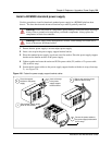
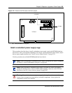
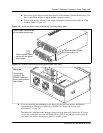
13 Install the power supply support bracket in the BCM400 platform base chassis (see Figure
129).
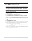
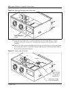
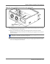
14 Position the redundant power supply cage in the base platform chassis. Make sure the power
supply module tray opening faces the rear of the platform base chassis.
15 Align the mounting holes in the redundant power supply cage with the screw holes in the
platform base chassis.
16 Attach the redundant power supply cage to the platform base chassis using the four chassis
mounting screws. Refer to Figure 136.
5
Secure the cables to the
power supply bracket
with the tie-wrap
Insert a tie-wrap in
the power supply
support bracket
lanclet
3
Gather and route the
cables to the
tie-wrap
4
Place power supply top side
down on flat surface
1
2
Place the support
bracket on the power
supply