


120 Chapter 4 Install, remove or replace the Media Bay Modules
P0993133 03
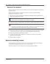
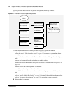
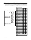
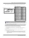
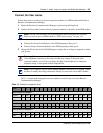
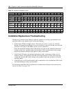
• Figure 70 shows the wiring pin-out for an BRIM S/T to the service provider.
Figure 70 BRIM S/T RJ45 wiring array
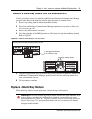
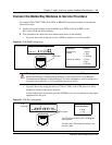
3 Insert the connector into the jack on the module.
Refer to the Business Communications Manager 3.0 Programming Operations Guide for steps
about changing the default settings for each line/loop.
4 You can now use the Unified Manager to configure the lines or sets associated with the
module. Refer to the Business Communications Manager 3.0 Programming Operations Guide.
Warning: The BRIM S/T must only be connected to an NT1 provided by the service
provider. The NT1 must provide a Telecommunication Network Voltage (TNV) to Safety
Extra Low Voltage (SELV) barrier.
8 7 6 5 4 3 2 1
BRIM S/T connector
RJ45 jacks
Pin #/connection
3- TX-
4 - RX-
4-RX-
5-RX+