


Chapter 9 Replace or Upgrade a Power Supply 201
Installation and Maintenance Guide
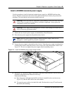
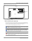
Install a BCM400 standard power supply
Use this procedure to install a functional standard power supply in a BCM400 platform base
chassis. The base function and advanced function trays must be partially removed.
1 Ensure the new power supply is an auto-adjust power supply.
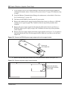
2 Insert a tie-wrap in the power supply support bracket lanclet.
3 Place the standard power supply (top down) on a flat surface. Place the power supply support
bracket on the bottom surface of the power supply.
4 Gather together and route the main card 20 Pin power cable (P1) and the +12v power cable
(P9) at the tie-wrap.
5 Secure the the power cables to the power supply support bracket with the tie-wrap (from step
2) - see Figure 128.
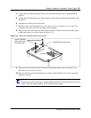
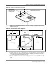
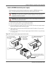
Figure 128 Fasten the power supply support bracket cables
Warning: Protect the hardware components against damage from electrostatic discharge.
Always wear a ground wrist strap before you handle components. Always place the
components in static-free container.
Warning: Power supply cable management is critical. Cable damage can result due to
loose or incorrectly positioned cables.
Insert a tie-wrap
in the power
supply support
bracket lanclet
3
Gather and route the power
cables at the tie-wrap
5
Secure the power cables to
the power supply bracket with
the tie-wrap
4
Place power supply upside
down on flat surface
1
2
Place the support
bracket on the power
supply