


292 Chapter 15 Troubleshooting
P0993133 03
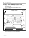
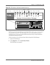
Access the System Status Monitor to Monitor LEDs
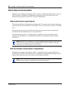
The LEDs on the Business Communications Manager base function tray are part of the System
Status Display (SSD) board.
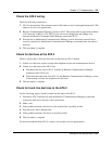
Figure 188 shows what the board looks like from inside the base function tray.
Figure 188 SSD board connections
Figure 189 shows what the LEDs look like on the outside of the base function tray. The labels in
the illustration indicate which part of the hardware each LED supports.
PCI Riser
card
connectors
Modem
card
Main card
DIMM
connector
I/O card
connector
BIOS
battery
Main card
connector
System status monitor board
mounting screws
SSM board
SSM Main
card
connector