


122 Chapter 4 Install, remove or replace the Media Bay Modules
P0993133 03
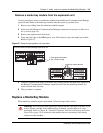
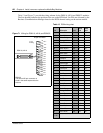
Table 13 and Figure 71 provide the wiring scheme for the DSM 16, 4X16 and DSM 32 modules.
The Sets heading indicates the position of the set on the BIX block. Set DNs are allocated by the
Business Communications Manager based on the DS30 channel setting on the station module.
Table 13 DSM wiring chart
Pin Wire color Port
Sets
1st
Sets
2nd
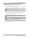
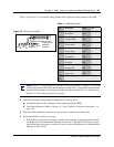
Figure 71 Wiring for DSM 16, 4X16, and DSM 32
26 White-Blue X01 1 17
1 Blue-White X01 1 17
27 White-Orange X02 2 18
2 Orange-White X02 2 18
28 White-Green X03 3 19
3 Green-White X03 3 19
29 White-Brown X04 4 20
4 Brown-White X04 4 20
30 White-Slate X05 5 21
5 Slate-White X05 5 21
31 Red-Blue X06 6 22
6 Blue-Red X06 6 22
32 Red-Orange X07 7 23
7 Orange-Red X07 7 23
33 Red-Green X08 8 24
8 Green-Red X08 8 24
34 Red-Brown X09 9 25
9 Brown-Red X09 9 25
35 Red-Slate X10 10 26
10 Slate-Red X10 10 26
36 Black-Blue X11 11 27
11 Blue-Black X11 11 27
37 Black-Orange X12 12 28
12 Orange-Black X12 12 28
38 Black-Green X13 13 29
13 Green-Black X13 13 29
39 Black-Brown X14 14 30
14 Brown-Black X14 14 30
40 Black-Slate X15 15 31
15 Slate-Black X15 15 31
41 Yellow-Blue X16 16 32
16 Blue-Yellow X16 16 32
42-40
17-25
no connections
T=Tip
R=Ring
8R
7R
6R
5R
4R
3R
2R
1 R
9R
10R
11R
12R
13R
14R
15R
16R
33T
32T
31T
30T
29T
28T
27T
26 T
34T
35T
36T
37T
38T
39T
40T
41T
DSM 16, 4X16
25-pair connector
DSM 32
The second 25-pair connector is
wired in the same sequence as the
first one