


Chapter 11 Install Telephones and Peripherals 245
Installation and Maintenance Guide
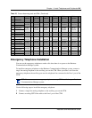
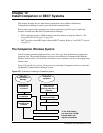
Emergency Telephone Installation
You can use the emergency telephone to make calls when there is no power to the Business
Communications Manager system.
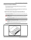
To install an emergency telephone on the Business Communications Manager system, connect a
single line analog telephone to the auxiliary port on the CTM. When you make a call from the
emergency telephone, the auxiliary port uses the telephone line connected to the Line 1 port of the
CTM.
Use the following steps to install the emergency telephone.
1 Connect a single line analog telephone to the auxiliary port on the CTM.
2 Connect an analog PSTN line cable to the Line 1 port of the CTM.
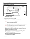
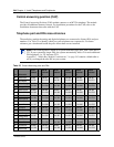
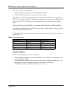
35 Red-Slate DN 230
Port 210
DN 246
Port 310
DN 262
Port 410
DN 278
Port 510
DN 294
Port 610
DN 310
Port 710
10 Slate-Red
36 Black-Blue DN 231
Port 211
DN 247
Port 311
DN 263
Port 411
DN 279
Port 511
DN 295
Port 611
DN 311
Port 711
11 Blue-Black
37 Black-Orange DN 232
Port 212
DN 248
Port 312
DN 264
Port 412
DN 280
Port 512
DN 296
Port 612
DN 312
Port 712
12 Orange-Black
38 Black-Green DN 233
Port 213
DN 249
Port 313
DN 265
Port 413
DN 281
Port 513
DN 297
Port 613
DN 313
Port 713
13 Green-Black
39 Black-Brown DN 234
Port 214
DN 250
Port 314
DN 266
Port 414
DN 282
Port 514
DN 298
Port 614
DN 314
Port 714
14 Brown-Black
40 Black-Slate DN 235
Port 215
DN 251
Port 315
DN 267
Port 415
DN 283
Port 515
DN 299
Port 615
DN 315
Port 715
15 Slate-Black
41 Yellow-Blue DN 236
Port 216
DN 252
Port 316
DN 268
Port 416
DN 284
Port 516
DN 300
Port 616
DN 316
Port 716
16 Blue-Yellow
TIP: You can connect an emergency telephone to every CTM installed on your Business
Communications Manager system.
Table 25 Cross referencing ports and DNs (Continued)
Pin Wire color
DS 30
channel
2
DS 30
channel
3
DS 30
channel
4
DS 30
channel
5
DS 30
channel
6
DS 30
channel
7