


Chapter 1 Introduction to the Business Communications Manager Platform Hardware 55
Installation and Maintenance Guide
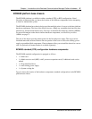
Base function tray interfaces
You can connect to the base function tray through the serial port or through a LAN port to perform
the system initialization. The data networking components connect the Business Communications
Manager system to your local area network (LAN) and/or the wide area network (WAN).
For initialization information, refer to “Use of a null modem serial cable” on page 137 and
“Connect the Ethernet crossover cable” on page 141.
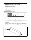
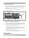
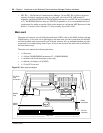
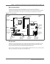
Figure 16 illustrates the base function tray ports for the BCM200 platform.
Figure 16 Base function tray faceplate ports
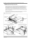
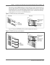
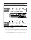
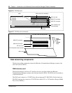
Base function tray system status display LEDs
A line of 10 LEDs display on the face of the base function tray (see Figure 17). The LEDs show
the current state of various hardware components. The Unified Manager contains a monitoring
tool, that allows you to determine the current condition of the LEDs from your computer. Refer to
“Access the System Status Monitor to Monitor LEDs” on page 292.
The system status LEDs indicate monitoring of the following:
• Power status (LED 1): Indicates the status of all power components. Green indicates normal
status. Red indicates an excessive voltage deficiency or a component failure (such as a
redundant power supply fan or module). An LED that monitors a component will also show a
fault in combination with the Power LED.
• Hard disk activity (LED 2): Green indicates hard disk access.
• System status (LED 3): Solid green indicates the system is normal and operational. Green
blink indicates one or more telephony services are not operational.
1
1 Six, non-blinking LEDs in the center indicates monitoring software is not active.
Modem port (North
America only)
Media services
card (MSC1b)
USB
ports
Ethernet
ports
COM
port
WAN card (field
upgrade)
System status display LEDs Reset button