


158 Chapter 6 Prepare Hardware for Maintenance or Upgrades
P0993133 03
5 Attach one end of the grounding strap to your wrist and the other end to a grounded metal
surface.
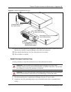
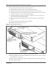
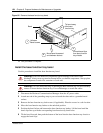
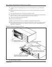
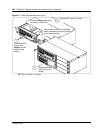
6 Remove the advanced function tray latch screws (see Figure 86). Place the screws in a safe
location.
7 Move the advanced function tray latches to the unlock position.
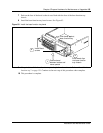
8 Grasp the advanced function tray latches and partially remove the unit from the platform base
chassis. Do not exert force on the hard disk power cables and connectors.
9 Disconnect hard disk power cable connectors.
10 Disconnect the IDE connector.
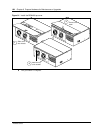
11 Remove the advanced function tray completely from the platform base chassis.
12 Place the advanced function tray on a flat, clean and static-free surface. If you need to remove
the hard disk component, refer to See “Remove a hard disk cage from a BCM400 platform
base chassis” on page 168
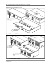
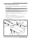
Figure 86 Remove the advanced function tray
13 This procedure is complete.
Unfasten advanced
function tray latch screws
1
Slide advanced function tray partially
away from the platform base chassis
3
2
4
Disconnect IDE cable
from I/O card
5
Disconnect power cables from
the hard disk or RAID card
Move advanced function tray
latches to the unlocked position