


Chapter 9 Replace or Upgrade a Power Supply 213
Installation and Maintenance Guide
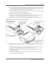
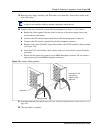
a Push on the power supply module until the face of the module is flush with the casing. You
hear a click when the power supply module is properly seated.
b Secure each module with the power supply locking nut (located on the right side of the
module). Refer to Figure 141.
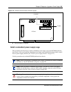
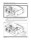
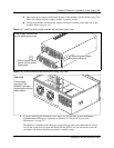
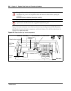
Figure 141 Install the power supply modules into the power supply cage
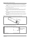
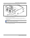
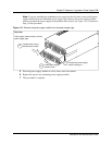
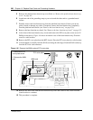
Figure 142 BCM400 platform redundant power supply (rear view)
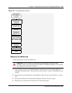
4 If you are installing the redundant power supply for the first time, restore the Business
Communications Manager to operation as described in “Restart the System after
Maintenance” on page 147.
The Business Communications Manager system starts up when you connect the AC power
cord. If the system does not start and the Red Power LED is on, you may need to press the
reset button on the base function tray panel to start the system.
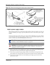
Power supply modules slide
into the power supply cage.
Push the power supply
module into the power
supply cage.
1
Fasten the power supply
module locking nut.
2
Rear view
Power supply
mounted in the
BCM400 redundant
feature option platform
base chassis