


Chapter 5 Business Communications Manager System Startup 131
Installation and Maintenance Guide
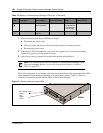
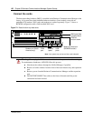
Connect the Data Networking Hardware
This section describes how to connect network cards to the Business Communications Manager
system.
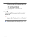
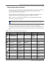
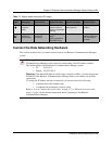
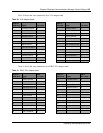
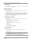
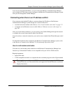
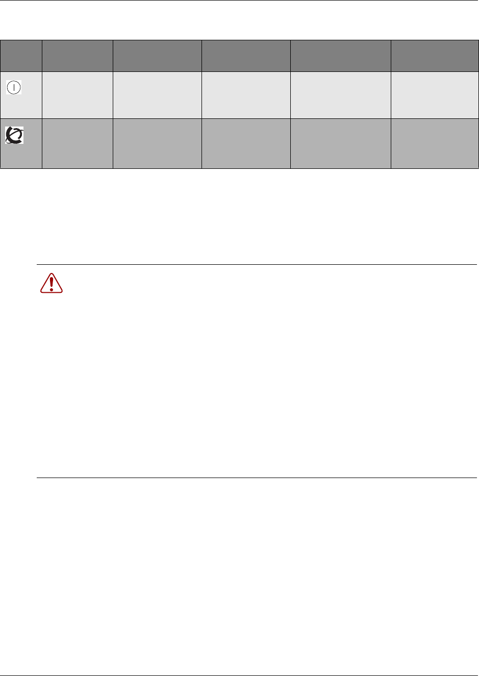
Table 17 Module power and status LED states
LED
Label
Description Green LED On Green LED Flash Red LED On (Only) Green LED Off
Indicates state
of system
power.
OK Check for hardware
problem with fan,
power or heat inside
housing
a minimum of 1 PS
needs attention
no power to the
module
Indicates
condition of
system status
all monitored
services are
functioning
in startup/shutdown
mode
check for problem
with MSC wiring
N/A not all services are
working, MSC may
not have started
correctly
Warning: Check with your network administrator before you connect the Business
Communications Manager to the network to ensure there are no IP address conflicts.
The default address for the Business Communications Manager system:
• IP: 10.10.10.1
• Subnet: 255.255.255.0
Warning: If the default IP address would create a network conflict, you must change the
IP address of the Business Communications Manager before you connect any network
connections.
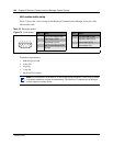
To change the IP address outside of a network, you can use one of the following:
• a terminal and a null modem cable
• a computer and an ethernet crossover cable
Refer to “Use of a null modem serial cable” on page 137 or “Ethernet crossover cable
usage” on page 140 for detailed instructions about connecting to the Business
Communications Manager.