


Telephony Hardware Selection and Settings 321
Installation and Maintenance Guide
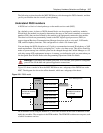
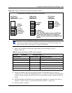
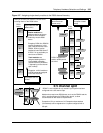
Figure 196 Space requirements for special media bay modules
1 Make a list of modules and the space requirements for each module you chose.
Refer to Table 50.
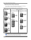
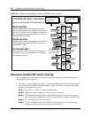
2 Set the bus numbers and offsets on the DIP switches of the module. Refer to Chapter 4,
“Install, remove or replace the Media Bay Modules,” on page 109. Note that you assign trunk
modules starting from the bottom DS30, and you assign station modules starting from the top
DS30.
3 Install the modules into the Business Communications Manager or expansion unit. Refer to
Chapter 4, “Install, remove or replace the Media Bay Modules,” on page 109.
4 This procedure is complete.
Note: If you choose a CTM8 or a 4X16 module, there are some restrictions about the
offsets you can choose. Refer to the DIP switch settings in “CTM switch settings” on
page 334 and “4X16 switch settings” on page 336 for details
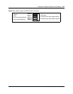
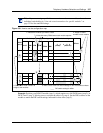
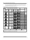
Table 50 Matching modules to DS30 channel capacity
DS30 split 2/6 (default) _____ 3/5 (extra IP lines) _____
Type of module Number required DS30s/offsets required
Combination and specialized media bay modules
Note: The FEM module requires a DS30 bus
for each port that is active. If all ports are
active, no other modules can be added to the
system.
4X16 module
2 DS30 buses/
offset set to 0, 1, 2, or 3
DECT module
1 DS30 bus/
offset set to 0
DDIM module
2 DS30 buses/
offset set to 0
1 offset of
1 full DS30
for lines
1 full DS30
for telephone
and equipment
connections
1 DECT
per DS30
(1 DECT per
system)
1 full DS30
for DTM
module
1 full DS30
for data module