


288 Chapter 14 Install Optional Telephony Equipment
P0993133 03
Activate auxiliary ringer programming
You can activate the auxiliary ringer by setting auxiliary ring for specific external lines and
Business Communications Manager telephones. Refer to the Business Communications Manager
3.0, Programming Operations Guide for programming details.
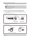
Connect the external paging system
You can connect a customer-supplied external paging system to provide paging over external
loudspeakers.
Ensure the paging system follows these guidelines:
• The paging output from the MSC is 100 mV rms across an input impedance of 600 :.
• The output level is 0 dBm0 with reference to 600 ohms, for a PCM encoded signal at 0 dBm.
There is no dc voltage across the page output terminals.
• The page output uses the tip and ring terminals of the jack. The sleeve terminal of the jack
connects to ground. You must use a stereo plug to connect the page signal output.
When you use the page signal output jack to connect an external paging amplifier, you also use the
page relay jack which contains a floating relay contact pair. The system uses this jack to control
the external paging amplifier.
• The contact pair has a switch capacity of 50 mA (non-inductive) at 40 V (maximum). You
must remove any inductive load on the output.
• The page relay contacts connect to the tip and ring terminals of the jack. The sleeve terminal of
the jack connects to ground. You must use a stereo plug to connect the page relay.
Use this procedure to install the external paging system using the installation instructions that
came with the paging system.
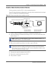
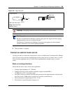
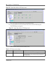
1 Connect the paging system audio input to the Page output on the MSC. Refer to Figure 185.
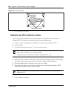
Figure 185 Audio input jack
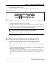
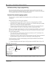
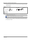
2 Connect the paging system relay to the Page relay output on the MSC. Refer to Figure 186.
Tip
Ring
Sleeve
Audio input jack
Tip: Page signal
Ring: Page signal
Sleeve: Ground
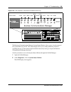
Page output
MSC Faceplate