


Chapter 4 Install, remove or replace the Media Bay Modules 123
Installation and Maintenance Guide
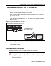
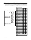
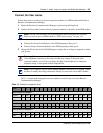
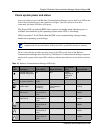
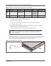
Table 14 and Figure 72 provide the wiring scheme for the eight pairs that connect to the ASM.
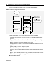
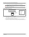
2 Install the telephones and peripheral equipment (if a new system):
a Attach the cables for the telephones to the connecting blocks (BIX).
b Install the telephones. Refer to Chapter 14, “Install Optional Telephony Equipment,” on
page 287.
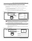
3 Plug the female amphenol connector into the interface on the front of the module.
4 Set up any mobile system you are using.
• Ensure the base stations are correctly installed and connected to the appropriate modules
on the Business Communications Manager. In the case of the NetVision wireless system,
ensure that the access point is correctly set up to connect to the Business Communications
Manager LAN or WAN.
Table 14 ASM wiring chart
Pin Wire color Port Set
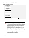
Figure 72 Wiring for an ASM 8
26 White-Blue X01 1
1 Blue-White X01 1
27 White-Orange X02 2
2 Orange-White X02 2
28 White-Green X03 3
3 Green-White X03 3
29 White-Brown X04 4
4 Brown-White X04 4
30 White-Slate X05 5
5 Slate-White X05 5
31 Red-Blue X06 6
6 Blue-Red X06 6
32 Red-Orange X07 7
7 Orange-Red X07 7
33 Red-Green X08 8
8 Green-Red X08 8
34-50 no connection
9-25
Note: Refer to “Line and extension numbers for specific modules” on page 332 to see the
relationship between the DS30 channel number and the DNs. Configuration information is
included in the chapters on setting up modules and DNs in the Business Communications
Manager 3.0 Programming Operations Guide.
8R
3
3T
32T
7R
31T
6R
30T
5R
29T
4R
28T
3R
27T
2R
26T
1R
25-pair female
amphenol
connector