


Chapter 9 Replace or Upgrade a Power Supply 193
Installation and Maintenance Guide
4 Attach one end of the grounding strap to your wrist and the other end to a grounded metal
surface.
5 Locate and disconnect the power supply cables from the I/O card, media bay backplane, and
hard disk.
6 Disconnect all cables from the I/O card.
7 Partially remove the base function tray (see “Remove the base function tray” on page 150).
Continue to the next step in this procedure when complete.
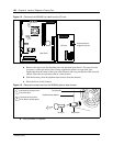
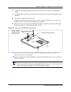
8 Remove the screws that secure the MSC guide bracket to the I/O card. Place the MSC guide
bracket and screws in a safe location (see Figure 118).
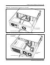
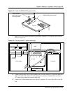
Figure 118 Remove the BCM200 MSC guide bracket
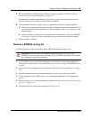
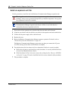
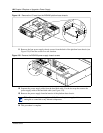
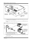
9 Remove the screws that secure the I/O card to the platform base chassis (see Figure 119).
Place the screws in a safe location.
10 Remove the I/O card from the platform base chassis. Place the I/O card in a safe, clean and
static-free location.
Note: Power supply and hard disk cables run underneath the I/O card. Remember the
location and position of the power supply and hard disk cables. You will need to route the
cables in the same manner when you re-install the power supply.
Unfasten BCM200
MSC guide bracket
mounting screws
BCM200 MSC guide bracket
I/O Card