


236 Chapter 10 Replace Data Cards and Processing Hardware
P0993133 03
1 If you still have access to the Unified Manager, shut down the system using the Shutdown
command. For details refer to “Shut down the system software” on page 145. Otherwise, skip
to step 2.
2 Set up the platform base hardware for maintenance, as described in “Shut down the system
hardware” on page 146.
3 Disconnect the Business Communications Manager from the AC power outlet.
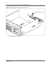
4 Disconnect any connectors from the front of the base function tray.
5 Remove the platform base chassis cover. See “Remove the platform base chassis top cover” on
page 161. Continue to the next step in this procedure when complete.
6 Attach one end of the grounding strap to your wrist and the other end to a grounded metal
surface.
7 Partially remove the base function tray from the platform base chassis. Ensure you do not
pinch, stretch or damage any cables.
8 Remove the base function tray bezel. See “Remove the base function tray bezel” on page 153.
Continue to the next step in this procedure when complete.
9 Remove the WAN card (if applicable). See “Remove the WAN card” on page 219. Continue to
the next step in this procedure when complete.
10 Detach the DS30 cable connectors from the MSC.
11 Remove the base function tray completely from the platform base chassis. Ensure you do not
pinch, stretch or damage any cables. See “Remove the base function tray” on page 150.
Continue to the next step of this procedure when complete.
12 Remove the media services card (see “Remove the media services card (MSC)” on page 225).
Continue to the next step of this procedure when complete.
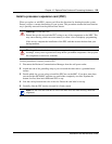
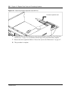
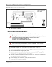
13 Carefully push down on the fastening tabs on either side of the DIMM you want to remove. As
you press down on the fastening tabs, the DIMM lifts out of the DIMM slot.
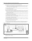
14 Grasp both ends of the DIMM with your fingertips. Lift the DIMM up and away from the
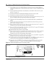
DIMM slot (see Figure 157 on page 236). Place the DIMM in a static-free container.
Figure 157 Remove and replace the dual in-line memory module
15 This procedure is complete.
Base function
tray front