


Chapter 6 Prepare Hardware for Maintenance or Upgrades 151
Installation and Maintenance Guide
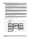
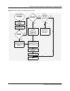
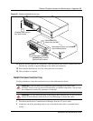
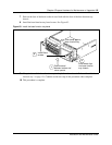
Figure 80 Remove the base function tray
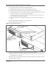
11 Remove the base function tray completely from the platform base chassis. Remove the base
function tray carefully to prevent damage to the cables and connectors.
12 Place the base function tray on a flat, clean and static-free surface.
13 This procedure is complete.
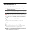
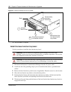
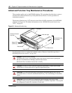
Install the base function tray
Use this procedure to insert the base function tray in the platform base chassis.
1 Disconnect the Business Communications Manager from the AC power outlet.
2 Attach one end of the grounding strap to your wrist and the other end to a grounded metal
surface.
Warning: Protect the hardware components against damage from electro-static
discharge. Always wear a ground wriststrap before you handle components. Always place
the components in static-free container or work area.
Warning: Use care when removing or inserting the Base function tray. Do not forcefully
remove or insert the base function tray. You could damage or stretch the cables.
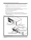
Slide base function tray
partially away from the
platform base chassis
3
2
Move base function tray latches to
the unlocked position
Disconnect DS30
cables from the MSC
Unfasten base function
tray latch screws
1
4