


Chapter 1 Introduction to the Business Communications Manager Platform Hardware 47
Installation and Maintenance Guide
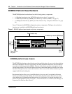
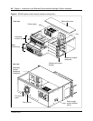
BCM400 platform base chassis
The BCM400 platform is available in either a standard (STD) or RFO configuration. Nortel
Networks recommends that you know the location of the different components before attempting
to install or maintain the system.
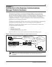
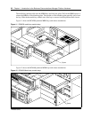
The BCM400 platform base chassis design provides multiple points of access to the base platform
hardware components. The front of the chassis has two, sliding tray assemblies that house the base
function tray and advanced function tray. Four bays accomodate the media bay modules (MBMs).
For more information on the chassis interior hardware components, see Media bay modules
(MBMs) on page 71.
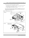
The rear of the chassis provides mount points for the fan and power supply. The top cover has
fixed and removable sections. Remove the rear portion of the cover to access the cabling, power
supply cage and hard disk components. Chassis adapters allow you to install the chassis in a server
rack. An optional wall mount bracket is available separately.
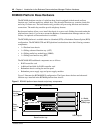
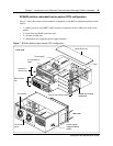
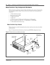
BCM400 standard (STD) configuration hardware components
The BCM400 standard configuration is equipped as follows:
• 1 x Main card
• 1 x Media services card (MSC) with 2 processor expansion cards (2 additional cards can be
added)
• 1 x Programed hard drive
• 1 x auto-sensing power supply
• 1 x System cooling fan
Figure 6 shows the location of the hardware components (standard configuration) in the BCM400
platform base chassis.