


138 Chapter 5 Business Communications Manager System Startup
P0993133 03
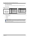
Null modem cable setup
Table 22 shows the correct wiring for the Business Communications Manager serial port of the
null modem cable.
Transmission parameters:
• 9600 bits per second
• 8 data bits
• no parity
•1 stop bit
• hardware flow control
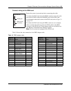
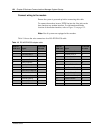
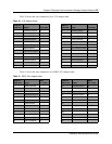
Table 22 Serial port pinout
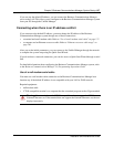
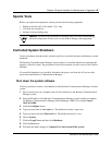
Figure 75 Serial pinout
Pin Signal Pin Signal
1 Data Carrier Detect (DCD) 6 Data Set Ready (DSR)
2 * Serial data in (RX) 7 Request to Send (RTS)
3 * Serial data out (TX) 8 Clear to Send (CTS)
4 Data Terminal Ready (DTR) 9 Ring Indicator (RI)
5 * Ground
* required connections
Note: For instructions about how to set the transmission parameters, refer to the terminal
or terminal emulation program documentation. The Business Communications Manager
system supports carriage return.
12345
6789