


Chapter 1 Introduction to the Business Communications Manager Platform Hardware 59
Installation and Maintenance Guide
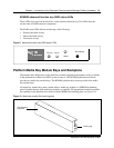
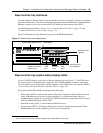
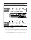
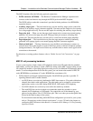
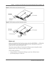
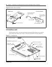
The MSC faceplate offers the following optional connections.
• DS256 connector (BCM400)— The Business Communications Manager expansion unit
connects to the base function tray through the DS256 jack on the MSC faceplate.
The DS256 cable to make this connection is provided with the purchase of an BCM1000e
expansion chassis.
• Auxiliary ringer jack — The base function tray uses the auxiliary ringer jack to control the
cadence of an auxiliary ringer (customer supplied). You must use this output in a low current,
low voltage application only. Do not use this output for switching the auxiliary ringer directly.
• Page relay jack — When you use the page signal output jack to connect an external paging
amplifier, you also use the page relay jack. The page relay jack connects a floating relay
contact pair. The base function tray uses this jack to control the external paging amplifier.
• Page output jack — The base function tray uses the page output to connect an internally
generated voice paging signal to an external paging amplifier (customer supplied).
• Music on hold jack — The base function tray uses the Music on hold input to connect an
external music source that supplies a signal to held lines (music on hold) or telephone speakers
(background music). The input source can be any available radio or music source approved for
connection to the network.
For directions on setting up these features, refer to “Media Service Card Connections” on page
287.
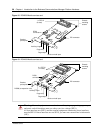
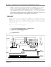
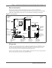
MSC IP call processing hardware
If your system requires a high volume of IP telephones and/or more IP trunks than the standard
eight trunks, you have the option to switch a DS30 bus setting on the MSC from providing service
for a media bay module, to providing digital processing service for additional IP telephones and/or
trunks. To ensure adequate data flow from the system, you can increase the number of PEC III
cards (BCM200 has a maximum of 2 cards, BCM400 has a maximum of 4).
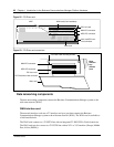
• DS30 channels are internal communication paths. Each DS30 bus provides a possible 32
signaling channels and 32 media channels.
— two DS30 buses are exclusively dedicated to MSC data resources. Five paths within these
channels have hard-coded applications. The other paths can be assigned to various data
applications such as voice mail, dialup ISDN WAN, VoIP trunks, or IP telephony.
— five DS30 channels are exclusively reserved for the media bay modules
— The sixth DS30 bus can be switched to accommodate media bay modules or more
channels for IP telephones or VoIP trunks. You control the use of the channel by your
choice of using either a 2/6 or 3/5 DS30 bus split. This is set when you run the Quick Start
Wizard at the initial startup of the system.
For more details about deciding which DS30 bus configuration you want for your system,
refer to “Determining module channel requirements” on page 320 and to the chapter on
configuring MSC Resources in the Business Communications Manager 3.0 Programming
Operations Guide.