


220 Chapter 10 Replace Data Cards and Processing Hardware
P0993133 03
5 Remove the platform base chassis top cover. Refer to “Remove the platform base chassis top
cover” on page 161.
6 Attach one end of the grounding strap to your wrist and the other end to a grounded metal
surface.
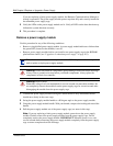
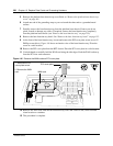
7 Partially remove the base function tray from the platform base chassis. Ensure you do not
pinch, stretch or damage any cables. If required, remove the base function tray completely
from the platform base chassis (see “Remove the base function tray” on page 150).
8 Remove the base function tray bezel. See “Remove the base function tray bezel” on page 153.
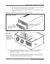
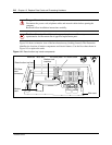
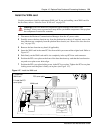
9 At the front of the base function tray, loosen and remove the PCI cover plate screw (use a #2
Phillips screwdriver). Figure 146 shows an interior view of the base function tray. Place the
screw in a safe location.
10 Remove the PCI cover plate from the BFT chassis. Place the PCI cover plate in a safe location.
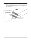
11 Use both hands to carefully hold the WAN card along the side edges. Push the WAN card away
from the PCI riser card connector.
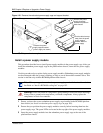
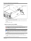
Figure 146 Remove the WAN card and PCI cover plate
12 Remove the WAN card from the base function tray. Place the card in a safe, static-free and
clean location or container.
13 This procedure is complete.
PCI cover plate
WAN card
1
2
1. Remove the PCI
cover plate screw
2. Remove the WAN
card